Download
1 / 86
2.06k likes | 4.26k Vues
UNIT III LOADERS AND LINKERS. This Unit gives you… Basic Loader Functions Machine-Dependent Loader Features Machine-Independent Loader Feature Loader Design Options Implementation Examples. BASIC DEFINITION.

E N D
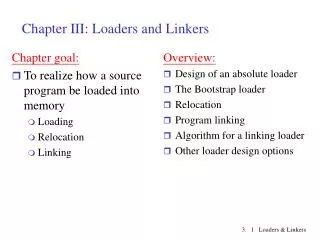
This Unit gives you… Basic Loader Functions Machine-Dependent Loader Features Machine-Independent Loader Feature Loader Design Options Implementation Examples
BASIC DEFINITION • Loading - which allocates memory location and brings the object program into memory for execution - (Loader) • Linking- which combines two or more separate object programs and supplies the information needed to allow references between them - (Linker) • Relocation- which modifies the object program so that it can be loaded at an address different from the location originally specified - (Linking Loader)
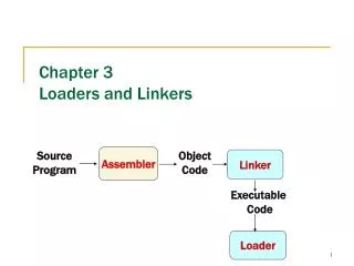
ROLE OF LOADER Source Program Translator Loader Object Program Object program ready for execution Translator – Assembler/Compiler Memory
ROLE OF LOADER Source Program Assembler Loader Object Program Object program ready for execution Memory
ROLE OF LOADER AND LINKER Memory Source Program Assembler Linker Object Program Object program ready for execution Executable Code Loader
WE KNOW… • Source Program – Assembly Language • Object Program - From assembler • - Contains translated instructions and data values from the source program • Executable Code - From Linker • Loader - Loads the executable code to the specified memory locations and code gets executed.
WE NEED…THREE PROCESSES • Loading - which allocates memory location and brings the object program into memory for execution - Loader • Linking- which combines two or more separate object programs and supplies the information needed to allow references between them - Linker • Relocation - which modifies the object program so that it can be loaded at an address different from the location originally specified - Linking Loader
BASIC LOADER FUNCTIONS • A Loader is a system program that performs the loading function • It brings object program into memory and starts its execution
TYPE OF LOADERS • absolute loader • bootstrap loader • relocating loader (relative loader) • direct linking loader
ABSOLUTE LOADER • Operation is very simple • The object code is loaded to specified locations in the memory • At the end the loader jumps to the specified address to begin execution of the loaded program
ROLE OF ABSOLUTE LOADER 1000 Absolute Loader Object Program Object program ready for execution 2000 Memory
ABSOLUTE LOADER • Advantage • - Simple and efficient • Disadvantage • - the need for programmer to specify the actual address • - difficult to use subroutine libraries • We have algorithm – next slide
Begin read Header record verify program name and length read first Text record while record type is <> ‘E’ do begin {if object code is in character form, convert into internal representation} move object code to specified location in memory read next object program record end jump to address specified in End record end
Space for 2 inch x 2 inch size Picture Space for 2 inch x 2 inch size Picture Format-1(a) (in PowerPoint)
OBJECT CODE REPRESENTATION • Each byte of assembled code is given using its hexadecimal representation in character form • Easy to read by human beings • Each byte of object code is stored as a single byte • Most machine store object programs in a binary form • We must be sure that our file and device conventions do not cause some of the program bytes to be interpreted as control characters
A SIMPLE BOOTSTRAP LOADER • When a computer is first tuned on or restarted, a special type of absolute loader, called bootstrap loader is executed • This bootstrap loads the first program to be run by the computer -- usually an operating system
EXAMPLE (SIC BOOTSTRAP LOADER) • The bootstrap itself begins at address 0 • It loads the OS starting address 0x80 • No header record or control information, the object code is consecutive bytes of memory
Begin X=0x80 (the address of the next memory location to be loaded Loop AGETC (and convert it from the ASCII character code to the value of the hexadecimal digit) save the value in the high-order 4 bits of S AGETC combine the value to form one byte A (A+S) store the value (in A) to the address in register X XX+1 End
SUBROUTINE GETC GETCAread one character if A=0x04 then jump to 0x80 if A<48 then GETC A A-48 (0x30) if A<10 then return A A-7 return
MACHINE-DEPENDENT LOADER FEATURES Absolute Loader – Simple and efficient Disadvantage is – programmer has to specify the starting address One program to run – no problem – not for several Difficult to use subroutine libraries efficiently
RELOCATION Execution of the object program using any part of the available and sufficient memory The object program is loaded into memory wherever there is room for it The actual starting address of the object program is not known until load time
RELOCATING LOADERS • Efficient sharing of the machine with larger memory and when several independent programs are to be run together • Support the use of subroutine libraries efficiently
METHODS FOR SPECIFYING RELOCATION • Use of modification record Refer Figure • Use of relocation bit Refer Figure • Each instruction is associated with one relocation bit • These relocation bits in a Text record is gathered into bit masks
MODIFICATION RECORD • Modification record • col 1: M • col 2-7: relocation address • col 8-9: length (halfbyte) • col 10: flag (+/-) • col 11-17: segment name • For complex machines • Also called RLD specification • - Relocation and Linkage Directory
HCOPY 000000 001077 T000000 1D17202D69202D48101036…4B105D3F2FEC032010 T00001D130F20160100030F200D4B10105D3E2003454F46 T001035 1DB410B400B44075101000…33200857C003B850 T0010531D3B2FEA1340004F0000F1..53C003DF2008B850 T00070073B2FEF4F000005 M00000705+COPY M00001405+COPY M00002705+COPY E000000 Figure Object program with relocation by Modification records
RELOCATION BIT • For simple machines • Relocation bit • - 0: no modification is necessary • - 1: modification is needed
RELOCATION BIT • For simple machines • Relocation bit • - 0: no modification is necessary • - 1: modification is needed
Twelve-bit mask is used in each Text record - col:10-12 – relocation bits • - since each text record contains less than 12 words • - unused words are set to 0 • - any value that is to be modified during relocation must coincide with one of these 3-byte segments - line 210
HCOPY 000000 00107A T0000001EFFC140033481039000036280030300015…3C0003 … T00001E15E000C00364810610800334C0000…000003000000 T0010391EFFC040030000030…30103FD8105D280030... T0010570A 8001000364C0000F1001000 T00106119FE0040030E01079…508039DC10792C0036... E000000 Object program with relocation by bit mask - FFC - all ten words are to be modified - E00 - first three records are to be modified
PROGRAM LINKING • Goal - Resolve the problems with EXTREF and EXTDEF from different control sections • Example - Program in Fig. 3.8 and object code in Figure (Refer) • Use modification records for both relocation and linking • - address constant • - external reference
EXTDEF (EXTERNAL DEFINITION • The EXTDEF statement in a control section names symbols, called external symbols, that are defined in this control section and may be used by other sections • Ex: EXTDEF BUFFER, BUFFEND, LENGTH (Refer Figure) • EXTDEF LISTA, ENDA (Refer Figure)
EXTREF (EXTERNAL REFERENCE) • The EXTREF statement names symbols used in this (present) control section and are defined elsewhere • Ex: EXTREF RDREC, WRREC (Refer Figure) EXTREF LISTB, ENDB, LISTC, ENDC (Refer Figure)
HOW TO IMPLEMENT THESE… • The assembler must include information in the object program that will cause the loader to insert proper values where they are required – in the form of • - Define record • - Refer record
DEFINE RECORD • Col. 1 D • Col. 2-7 Name of external symbol defined in this control section • Col. 8-13 Relative address within this control section (hexadecimal) • Col.14-73 Repeat information in Col. 2-13 for other external symbols • - D LISTA 000040 ENDA 000054 • - D LISTB 000060 ENDB 000070
REFER RECORD • Col. 1 R • Col. 2-7 Name of external symbol referred to in this control section • Col. 8-73 Name of other external reference symbols R LISTB ENDB LISTC ENDC R LISTA ENDA LISTC ENDC R LISTA ENDA LISTB ENDB
0000 PROGA START 0 EXTDEF LISTA, ENDA EXTREF LISTB, ENDB, LISTC, ENDC . . 0020 REF1 LDA LISTA 03201D 0023 REF2 +LDT LISTB+4 77100004 0027 REF3 LDX #ENDA-LISTA 050014 . . 0040 LISTA EQU * 0054 ENDA EQU * 0054 REF4 WORD ENDA-LISTA+LISTC 000014 0057 REF5 WORD ENDC-LISTC-10 FFFFF6 005A REF6 WORD ENDC-LISTC+LISTA-1 00003F 005D REF7 WORD ENDA-LISTA-(ENDB-LISTB) 000014 0060 REF8 WORD LISTB-LISTA FFFFC0 END REF1
0000 PROGB START 0 EXTDEF LISTB, ENDB EXTREF LISTA, ENDA, LISTC, ENDC . . 0036 REF1 +LDA LISTA 03100000 003A REF2 LDT LISTB+4 772027 003D REF3 +LDX #ENDA-LISTA 05100000 . . 0060 LISTB EQU * 0070 ENDB EQU * 0070 REF4 WORD ENDA-LISTA+LISTC 000000 0073 REF5 WORD ENDC-LISTC-10 FFFFF6 0076 REF6 WORD ENDC-LISTC+LISTA-1 FFFFFF 0079 REF7 WORD ENDA-LISTA-(ENDB-LISTB) FFFFF0 007C REF8 WORD LISTB-LISTA 000060 END
0000 PROGB START 0 EXTDEF LISTB, ENDB EXTREF LISTA, ENDA, LISTC, ENDC . . 0036 REF1 +LDA LISTA 03100000 003A REF2 LDT LISTB+4 772027 003D REF3 +LDX #ENDA-LISTA 05100000 . . 0060 LISTB EQU * 0070 ENDB EQU * 0070 REF4 WORD ENDA-LISTA+LISTC 000000 0073 REF5 WORD ENDC-LISTC-10 FFFFF6 0076 REF6 WORD ENDC-LISTC+LISTA-1 FFFFFF 0079 REF7 WORD ENDA-LISTA-(ENDB-LISTB) FFFFF0 007C REF8 WORD LISTB-LISTA 000060 END
H PROGA 000000 000063 D LISTA 000040 ENDA 000054 R LISTB ENDB LISTC ENDC . . T 000020 0A 03201D 77100004 050014 . . T 000054 0F 000014 FFFF6 00003F 000014 FFFFC0 M000024 05+LISTB M000054 06+LISTC M000057 06+ENDC M000057 06 -LISTC M00005A06+ENDC M00005A06 -LISTC M00005A06+PROGA M00005D06-ENDB M00005D06+LISTB M00006006+LISTB M00006006-PROGA E000020
H PROGB 000000 00007F D LISTB 000060 ENDB 000070 R LISTA ENDA LISTC ENDC . . T 000036 0B 03100000 772027 05100000 . . T 000007 0F 000000 FFFFF6 FFFFFF FFFFF0 000060 M000037 05+LISTA M00003E 06+ENDA M00003E 06 -LISTA M000070 06 +ENDA M000070 06 -LISTA M000070 06 +LISTC M000073 06 +ENDC M000073 06 -LISTC M000073 06 +ENDC M000076 06 -LISTC M000076 06+LISTA
H PROGC 000000 000051 D LISTC 000030 ENDC 000042 R LISTA ENDA LISTB ENDB . T 000018 0C 03100000 77100004 05100000 . T 000042 0F 000030 000008 000011 000000 000000 M000019 05+LISTA M00001D 06+LISTB M000021 06+ENDA M000021 06 -LISTA M000042 06+ENDA M000042 06 -LISTA M000042 06+PROGC M000048 06+LISTA M00004B 06+ENDA M00004B 006-LISTA M00004B 06-ENDB M00004B 06+LISTB M00004E 06+LISTB M00004E 06-LISTA E
Program Linking Example • Refer Figure 3.5.2 • Load address for control sections • PROGA 004000 63 • PROGB 004063 7F • PROGC 0040E2 51
Load address for symbols • LISTA: PROGA+0040=4040 • LISTB: PROGB+0060=40C3 • LISTC: PROGC+0030=4112 • REF4 in PROGA • ENDA-LISTA+LISTC=14+4112=4126 • (ENDA-LISTA = 14 (4054-4040) • T0000540F000014FFFFF600003F000014FFFFC0 • M00005406+LISTC
Figure 3.5.1:Programs form the above figure after linking and loading
Figure 3.5.2: relocation and linking operations performed on REF4 from PROGA
ALGORITHM AND DATA STRUCTURES FOR A LINKING LOADER • Linking Loader uses two-passes logic • - Pass 1: assign addresses to all external symbols • - Pass 2: perform the actual loading, relocation, and linking • ESTAB (external symbol table) – main data structure for a linking loader
PROGRAM LOGIC FOR PASS 1 • Pass 1: • - Assign addresses to all external symbols • Variables & Data structures • - PROGADDR (program load address) from OS • - CSADDR (control section address) • - CSLTH (control section length • - ESTAB • Refer Algorithm for Pass 1 of LL in Fig. 3.11(a) • - Process Define Record