Download
1 / 16
160 likes | 190 Vues
ECE 3430 – Introduction to Microcomputer Systems University of Colorado at Colorado Springs. Lecture #5 Agenda Today STORE instructions HC11 I/O MicroStamp I/O MicroStamp Memory Map Lab Introduction. STORE Instructions.

E N D
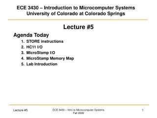
ECE 3430 – Introduction to Microcomputer SystemsUniversity of Colorado at Colorado Springs Lecture #5 Agenda Today • STORE instructions • HC11 I/O • MicroStamp I/O • MicroStamp Memory Map • Lab Introduction ECE 3430 – Intro to Microcomputer Systems Fall 2009
STORE Instructions STORE – A store instruction will move information from the CPU registers and put the data into a memory address. - A store instruction uses only direct, extended, or indexed addressing. In each of these addressing modes, we are defining where the information is to be stored. (A,B,D,X,Y,SP) Memory Store instructions: STAA – store accumulator A to memory (8-bit) STAB – store accumulator B to memory (8-bit) STD – store accumulator D to memory (16-bit) STX – store index register X to memory (16-bit) STY – store index register Y to memory (16-bit) STS – store stack pointer to memory (16-bit) ECE 3430 – Intro to Microcomputer Systems Fall 2009
STORE Instructions Ex) Store ACCA to memory location $E100 STAA $E100 Extended Addressing (EXT) Ex) Store ACCB to memory location $00FF STAB $FF Direct Addressing (DIR) Ex) Store ACCD to memory location $E101 and $E102 LDX #$E100 STD 1,X Indexed Addressing Using X (INDX) Or LDY #$E101 STD 0,Y Indexed Addressing Using Y (INDY) ECE 3430 – Intro to Microcomputer Systems Fall 2009
HC11 Input and Output (I/O) HC11 Ports - • There are many varieties of the HC11—each of which can have different I/O definitions. • Our version of the HC11 has 4, 8-bit I/O registers. These I/O registers are called ports. • Ports are data latches that exist outside of the CPU core (but still inside the microcontroller). Each port is assigned a designated memory location. When a load or a store operation targets the address belonging to a port register, the data is read from or written to the data bus—reading input pins and/or adjusting the state of output pins. Port A ($0000) = [7:0] = [bi, out, out, out, bi, in, in, in] Port B ($0004) = [7:0] = all bi-directional Port C ($0003) = [7:0] = all bi-directional Port D ($0008) = [7:0] = all bi-directional NOTE: Any accumulators/registers contents can be stored to any port. In other words there is no association between PORTA and ACCA, PORTB and ACCB, etc. ECE 3430 – Intro to Microcomputer Systems Fall 2009
HC11 Input and Output (I/O) Therefore, gathering data from an external device or writing data to an external device is accomplished by loading from and storing to dedicated memory locations. For this reason, the HC11 uC is referred to as a memory-mapped architecture. We are using the MC68HC11D3 in a 40-pin package. • These ports (A, B, C, D) are brought out to pins on the HC11 package. • The pins corresponding to ports B and C are multiplexed with the data and address bus in order to reduce total pin count. • The address and data bus are brought out to pins so that additional memory can be added (in additional to memory available within the uC). ECE 3430 – Intro to Microcomputer Systems Fall 2009
Microstamp Microstamp - This is the target board that the HC11 is loaded on. The target board is a printed circuit board (PCB) that contains all of the necessary peripheral circuitry (crystal oscillator [clock], power regulators, RS-232 transceiver [for serial port], etc.) Our target system is the Microstamp11 from Technological Arts (see the web page for link). The Microstamp provides: 1) Connectors for I/O, and power. 2) Crystal oscillator [XTAL] (8MHz, E-Clock = 2MHz) 3) 8KB EEPROM 4) Voltage Regulator 5) RS-232 transceiver (used to interface to a host computer for programming. 6) Reset button 7) Mode switches – programming mode vs. run mode EEPROM protected vs. unprotected mode ECE 3430 – Intro to Microcomputer Systems Fall 2009
Microstamp Microstamp I/O - The Microstamp does not bring all of the ports out to connectors. It only brings out the following: Port A ($0000) = [7:0] = [bi, out, out, out, bi, in, in, in] Port D ($0008) = [5:0] = [bi, bi, bi, bi, bi, bi] In the lab we have a total of 14 I/O pins available on the Microstamp 8 bi, 3 in, 3 out. Port B and C are not available because we have an 8K external EEPROM using the address and data bus. Memory Map • The HC11 is a memory-mapped architecture—all I/O is done as though you are interacting with a memory device. • The Microstamp maps its external EEPROM into a particular memory range. • The HC11 has some internal RAM which is also mapped to a particular memory range. ECE 3430 – Intro to Microcomputer Systems Fall 2009
Microstamp Microstamp Memory Map • We store our programs in the 8KB EEPROM (this EEPROM is part of the Microstamp, not the HC11). • We don’t use the 32KB expandable EEPROM. • We don’t have any external RAM. • We use the internal RAM for data. • The internal register block is for setup and I/O (I/O ports are mapped in here). • To find the address of an internal register, look in the pink book. • To get data in and out of the HC11, we read and write to the ports. Remember that not all port bits are available on the Microstamp. ECE 3430 – Intro to Microcomputer Systems Fall 2009
Microstamp Power Connector (connect to bench supply, 9V battery, or wall wart) Reset Button External EEPROM (Program Storage) Mode Switches (x2) HC11 Microcontroller (Internal RAM and Ports) Connection Harness for I/O Devices (Ribbon Cable to Breadboard) Voltage Regulator Everything needing power RS-232 Transceiver RS-232/Serial Connector (to connect to host computer) From Outside World ECE 3430 – Intro to Microcomputer Systems Fall 2009
Microstamp How do we program it? • We create a text file that contains instructions and assembler directives. This is called an assembly source file. These files are given a ASM file extension (lab1.asm). • We use the HC11 cross-assembler (asm11.exe) to convert the assembly code into machine code. The output of the cross-assembler is the object code. • The cross-assembler creates the machine code in a file with an S19 extension (lab1.s19). • The cross-assembler can (optionally) create a listing file which we will talk about later (lab1.lst). • We use a Windows-based downloading program to download the S19 file into the EEPROM on the Microstamp (ms11download.exe). This executable utility communicates through the RS-232 interface and writes new contents to the EEPROM. This is the only time the EEPROM can be changed (during normal operation it is read-only). NOTE: In lab there will be an additional step between 2 and 3 above where extra libraries (code that you didn’t write) will be linked into your S19 file prior to downloading. These libraries give your code the ability to be debugged and to interact directly with the host computer. A Windows-based utility program does this linking (linkutils.exe). ECE 3430 – Intro to Microcomputer Systems Fall 2009
Microstamp Interaction with PC A windows utility called HyperTerminal can be used to interface to the HC11 via the serial cable. HyperTerminal is a terminal emulator: • When you press keys on the PC’s keyboard, commands are sent to the HC11 via the serial cable. The commands move through the RS-232 transceiver and then communicate with the HC11 via the serial communication interface (SCI). • When certain commands are issued in the code running on the HC11, data can be sent back to the host PC through the serial cable. Ex) The HC11 can print strings of data to the PC’s terminal window. ECE 3430 – Intro to Microcomputer Systems Fall 2009
Microstamp Interaction with PC I recommend using my terminal program (comterm.exe)—rather than the Microsoft-provided HyperTerminal. It gives you the option to do some things you can’t with HyperTerminal—like allowing the HC11 to write to your hard drive. Download it from the lab web page (along with the other utilities): • HC11 Cross-Assembler (asm11.exe) • Utility Library Linker (linkutils.exe) • MicroStamp11 Downloader (ms11download.exe) • Terminal program (comterm.exe) ECE 3430 – Intro to Microcomputer Systems Fall 2009
Microstamp Interaction with PC The special libraries you link into your S19 file provide subroutines that interact with the host PC. For this class you won’t have to worry about the specifics of how that is done. • Subroutines will be discussed later in this course. • For now, think of a subroutine as a special command you can issue to have “something” done for you. • Subroutines are called via the JSR instruction (which stands for jump to subroutine). The operands provide the address of where this subroutine lives in memory: JSR OUTA ; outputs the contents of ACCA to the PC terminal JSR PAUSE ; waits until a key is pressed on PC keyboard before ; proceeding with the next instruction ECE 3430 – Intro to Microcomputer Systems Fall 2009
Lab Introduction For lab #1 you are wiring up a fixed circuit which you will use for the rest of this semester. Your breadboard contains 8 LEDs, 4 toggle switches, and a pushbutton (for generating interrupts). We are not concentrating on the breadboard too much this semester (take ECE 3440 if you want to interact with cooler things). This class will focus more on the internals of the HC11. The breadboard is only there to give us some form of I/O to interact with: LEDs = actuators Toggle switches, pushbutton = sensors The LEDs, toggle switches, and pushbutton are wired to a J10 connector. A ribbon cable connects to the J10 connector and provides communication with the Microstamp. Power is provided to your breadboard via the J10 connector. Never attach your breadboard to power supplies! ECE 3430 – Intro to Microcomputer Systems Fall 2009
Lab Introduction As you are wiring up lab #1, think about the active-high and active low sensor/actuator techniques we talked about. Once you are wired up, you will run some code on the HC11 that is already written and assembled into an S19 file. You will download the S19 file via the ms11download.exe utility. Then close the utility program and open comterm.exe (they both cannot be open at the same time). When the test code runs on the HC11, it will exercise the sensors and actuators on your breadboard—as well as interact with the host PC through the serial cable. This program allows you to verify that your hardware works and you didn’t make any wiring mistakes. ECE 3430 – Intro to Microcomputer Systems Fall 2009
Lab Introduction Read the lab introduction section BEFORE you come to each lab this semester. Many of your questions may be answered in the introduction. The introduction will help you understand what you are doing. Your lab instructor will get angry if you ask questions that are answered in the introduction section. To sum it up, be prepared! ECE 3430 – Intro to Microcomputer Systems Fall 2009