Download
1 / 18
180 likes | 366 Vues
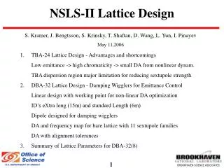
Lattice design for IBS dominated beams. Yannis PAPAPHILIPPOU IBS ’07 – Intra Beam Scattering mini workshop, The Cockcroft Institute, Daresbury, UK. August 28-29 th , 2007. Introduction.

E N D
Lattice design for IBS dominated beams Yannis PAPAPHILIPPOU IBS ’07 – Intra Beam Scattering mini workshop, The Cockcroft Institute, Daresbury, UK. August 28-29th, 2007
Introduction • Damping rings necessitate a small output emittance and a good transmission of the very intense e+,e-beam • Among the most important limitations, is the effect of intra-beam scattering (IBS) which can lead to a growth of the 6-dimensional phase space emittances • From the lattice design point of view, measures should be taken to reduce the effect of IBS • One would like to iterate the lattice design features until a robust optimum is found with respect to emittance with IBS, including other optics and non-linear dynamics considerations • Systematic approach of damping ring design was given by P. Emma, T. Raubenheimer (PRSTAB, 2001) • Optimisation of CLIC damping rings was performed by M. Korostlelev (PhD thesis, 2006) for various ring parameters • Following these two previous studies, particular emphasis will be given in the influence of the IBS on different ring parameters • Some ideas for a strategy for ring parameter optimisation including IBS will be presented IBS ’07, Y. Papaphilippou
Input parameters • Dictated by design criteria of the collider (e.g. luminosity), injected beam characteristics or compatibility with the downstream system parameters (e.g. bunch compressors) • Changes of major linear collider systems (RF structure) require re-adaptation of the parameters, and damping ring design reiteration IBS ’07, Y. Papaphilippou
Ring energy • Choice dictated by spin tune (half integer) for maintaining high-spin polarisation • Frozen on early design stage • Advantage of lower energies: • For same equilibrium emittance i.e. smaller circumference and radiated power (cost), high momentum compaction (longitudinal stability). • Advantages of higher energy • For fixed damping fraction due to wigglers and wiggler peak field, i.e. easier magnetic design (lower main field) and smaller total wiggler length • IBS emittance growth increases with energy • IBS growth rate is energy independent. • It may become more important in higher energies as compared to the damping rate if number of stored bunch trains is increased with the circumference. Than the damping time scales as (P. Emma, T. Raubenheimer PRSTAB, 2001) IBS ’07, Y. Papaphilippou
Momentum compaction factor and number of cells • Larger momentum compaction factor produces higher bunch length, which relaxes collective effects including IBS, by reducing the charge density • Maximum value constrained by bunch compression requirements • Momentum compaction factor scales as (P. Emma, T. Raubenheimer PRSTAB, 2001) whereas the number of TME cells are • The maximum momentum compaction is achieved for IBS ’07, Y. Papaphilippou
Lattice choice • Usually racetrack configuration with TME arcs and damping wigglers in the straights • NLC DR was based on lattice with 32 TME arc cells and wigglers of 62m total length (A.Wolski et al. 2003) • ILC has a large ring of more than 6km for accepting large number of bunches with reduced e-cloud effect • TME and FODO lattice considered (A.Wolski et al. 2007)
Phase advance choice • Optimum horizontal phase advance of cells for minimising zero current emittance is fixed (284o for TME cells) • Vertical phase advance is almost a free parameter • First iteration based on lattice considerations, i.e. comfortable beta functions and relaxed quadrupole strengths and chromaticity • Low horizontal phase advance gives increased momentum compaction factor (high dispersion) but also chromaticity (M. Korostelev, PhD Thesis EPFL, 2006) IBS ’07, Y. Papaphilippou
Phase advance choice with IBS Horizontal phase advance for minimum horizontal emittance with IBS, is found in an area of small horizontal beta and moderate dispersion functions (between 1.2-1.3π, for CLIC damping rings) Optimal vertical phase advance quite low (0.2π) The lowest longitudinal emittance is achieved for high horizontal and low vertical phase advances The optimal point may have to be compromised due to chromaticity considerations and dynamic aperture optimisation (M. Korostelev, PhD Thesis EPFL, 2006) 29/08/2007 IBS ’07, Y. Papaphilippou 8
Circumference Drifts + dipoles • Usually chosen big enough to accommodate number of bunch trains • Drift space increase may be essential for establishing a realistic lattice, reserving enough space for instrumentation and other equipment • For constant number of dipoles (TME cells), zero equilibrium emittance is independent of circumference • Normalised emittance with IBS increases with circumference (no wigglers) • When dipole lengths are increased along with drifts, emittance grows due to increase of damping time (inversely proportional to radiation integral I2 which decreases with length) • When only drifts are increased, smaller emittance growth due to increase of optics functions • Impact on chromaticity + non-linear optimisation • Some compensation may be achieved due to increase of bunch length with circumference (momentum compaction factor) Only Drifts Drifts + dipoles Only Drifts IBS ’07, Y. Papaphilippou (M. Korostelev, PhD Thesis EPFL, 2006)
Damping wiggler parameters • Damping wigglers are used to increase radiation damping and reduce the effect of IBS in order to reach target emittances • The total length of wigglers is chosen by its dependence with the peak wiggler field and relative damping factor • The optics of the wiggler straight section are optimised, as for the arcs. in order to both decrease the final emittance, keeping the optics functions and chromatic ring properties reasonable • For higher wiggler field and smaller period the transverse emittance computed with IBS gets smaller • The longitudinal emittance has a different optimum but it can be controlled with the RF voltage • The choice of the wiggler parameters is finally dictated by their technological feasibility (M. Korostelev, PhD Thesis EPFL, 2006) IBS ’07
RF voltage and frequency • The smallest transverse emittance is achieved for the lowest RF frequency and higher voltage, while keeping the longitudinal emittance below 5000 eV.m • Reversely the longitudinal emittance is increased for small RF frequency IBS ’07, Y. Papaphilippou
Coupling and alignment tolerances • Most critical for low (vertical) emittance tuning • Detailed study and comparison made by A. Wolski et al. for NLC • For ILC the following tolerances were considered, for a robust behaviour of the lattice (J.Jones EPAC2006) • For CLIC similar tolerance considered (M.Korostelev PhD thesis 2006) achieving 0.1% of coupling and 0.25μm of dispersion invariant ILC IBS ’07, Y. Papaphilippou 12
Coupling correction • Coupling effect of wigglers should be included in simulations • Correction with dispersion free steering (orbit and dispersion correction) • Skew quadrupole correctors for correcting dispersion in the arc and emittance minimisation • Iteration of dynamic aperture evaluation and optimisation after correction • In CLIC damping rings, the effect of vertical dispersion is dominant IBS ’07, Y. Papaphilippou
Bunch charge • Approximate scaling laws can be derived for a given damping ring design • For example, for the CLIC damping rings, the horizontal normalized emittance scales approximately as • The above relationship is even more exact when the longitudinal emittance is kept constant (around 5000 eV.m, in the case of the CLIC damping rings) • Vertical and longitudinal emittance are weakly dependent on bunch charge, and almost linear with each other IBS ’07, Y. Papaphilippou 14
Dependence on longitudinal emittance • By relaxing the requirement in the longitudinal emittance the horizontal emittance can be further reduced, while the vertical one stays almost constant, for the same bunch charge • This requires relaxing constraints of other injector systems, i.e. bunch compressor for the CLIC damping rings IBS ’07, Y. Papaphilippou 15
Strategy for lattice design in IBS dominated beams Input and target parameters: injected and extracted emittance, bunch charge, number of bunches Energy and Lattice choice (TME, NBA, …), momentum compaction factor Chromaticity correction, non-linear optimisation, dynamic aperture Optics functions parameter space scan for minimising emittance with IBS while keeping low chromaticity Choosing damping wigglers parameters, design straight section optics and evaluation of emittance with IBS Alignment tolerances, orbit and coupling correction and final emittance with IBS Collective effects IBS ’07, Y. Papaphilippou
Numerical tools • MAD for optics design • IBS growth rates computed using extended formalism of Conte and Martini • ZAP includes 2D formalism of Bjorken and Mtingwa • BETA for coupling correction, and equilibrium emittance minimisation • SAD code for optics design and equilibrium emittance with IBS (including coupling) • Mathematica, for symbolic evaluation of IBS integrals + optics calcuations (e.g. MADto Mathematica package by J.Jowett) • Matlab, for numerical evaluation of IBS integrals and interface with the optics design using the accelerator toolbox • … IBS ’07, Y. Papaphilippou
Concluding remarks • In the case of IBS dominated beams, all lattice parameters can be optimised for reaching the target emittance including IBS • The effect of IBS is evaluated “a posteriori”, i.e. after setting up the basic features of the lattice • An iterative process can be used in order to scan the full parameter space and reach the optimum, using numerical tools • Lack of a unique tool for executing all the optimisation steps and reiterate if needed. A MATLAB based package using the accelerator toolbox should be a good choice • An interesting idea would be to derive analytically the optics parameters for reaching minimum IBS dominated emittance (J.Jowett) in selected lattices (FODO, TME,…) IBS ’07, Y. Papaphilippou