VME Crates & Processors: Configuration and Troubleshooting Guide
50 likes | 124 Vues
Learn about accessing VME crates via CANBUS interface, configuring address & communication speed, rebooting processors, and resolving common issues. Detailed instructions provided.

VME Crates & Processors: Configuration and Troubleshooting Guide
E N D
Presentation Transcript
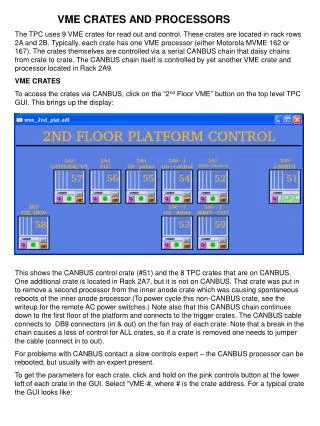
VME CRATES AND PROCESSORS The TPC uses 9 VME crates for read out and control. These crates are located in rack rows 2A and 2B. Typically, each crate has one VME processor (either Motorola MVME 162 or 167). The crates themselves are controlled via a serial CANBUS chain that daisy chains from crate to crate. The CANBUS chain itself is controlled by yet another VME crate and processor located in Rack 2A9. VME CRATES To access the crates via CANBUS, click on the “2nd Floor VME” button on the top level TPC GUI. This brings up the display: This shows the CANBUS control crate (#51) and the 8 TPC crates that are on CANBUS. One additional crate is located in Rack 2A7, but it is not on CANBUS. That crate was put in to remove a second processor from the inner anode crate which was causing spontaneous reboots of the inner anode processor.(To power cycle this non-CANBUS crate, see the writeup for the remote AC power switches.) Note also that this CANBUS chain continues down to the first floor of the platform and connects to the trigger crates. The CANBUS cable connects to DB9 connectors (in & out) on the fan tray of each crate. Note that a break in the chain causes a loss of control for ALL crates, so if a crate is removed one needs to jumper the cable (connect in to out). For problems with CANBUS contact a slow controls expert – the CANBUS processor can be rebooted, but usually with an expert present. To get the parameters for each crate, click and hold on the pink controls button at the lower left of each crate in the GUI. Select “VME-#, where # is the crate address. For a typical crate the GUI looks like:
This shows the voltages and currents for the crate, the fan speed, the temperatures and some status bits. (Note that most of the these readings for the crates are accurate but there are a few cases where a readout is obviously incorrect.) We always run the fans at the max (typically 3120 rpm). Clicking on the “Sysreset” button on this GUI sends a signal to the backplane telling the processor to reboot. (See below for other reboot methods). You can also turn the crate on/off by using the GUI buttons. These emulate momentary contact buttons, so multiple clicks may be needed to turn on/off. I rarely needed to power cycle a crate – it was sometimes necessary if an interface card in the crate got into a funny state that was not cleared by a reboot. Each crate consists of a card cage, a fan tray, which also contains the on/off switch, CANBUS input/output and some control switches, and a power supply. Both the power supply and fan tray can be swapped in place for most of these crates – see Dan Padrazo for spares and help. Note: when swapping a fan tray, it is necessary to set the CANBUS address and communication speed BEFORE plugging in the CANBUS cables. The address and comm speed can be set with the front panel control switches. The comm speed used for this chain is 250 kbaud. The address and comm speed can be set by using the “mode select” and “addr” toggle switches on the fan tray. You can also see the various voltages, fan speed etc.
VME PROCESSORS Typically the VME processor for each crate is either a Motorola MVME 162 or 167 and sits in the left most slot. Crate 58 is the only remaining crate with 2 processors installed – one controls the HDLC readout for the RDOs and it may be removed for DAQ1000 – consult the slow controls group. To communicate to the outside world a so-called transition module is mounted in the back of each crate. A cable connects the module to the backplane at the same position in the crate as the processor. The transition module usually has two cable attached – an ethernet cable and a serial RS232 cable. Some modules have an additional RS232 cable that is used to readout some interface box (i.e. TPC temperature). The ethernet cables go to an ethernet switch located in the bottom of Rack 2A8. The processor needs to attach to the ethernet to boot (they used to boot from SC3, but are being moved over to SC5 (LINUX)) One can also log in to the processor using ethernet, although this is not the preferred method for amateurs. The RS232 cables also go to Rack 2A8 to a specific port on a terminal server. The standard way to reboot is to log in to the processor via the RS232 line – one can then watch the boot dialog and check for problems. Specifically, to reboot a processor: Log in to sc5.starp.bnl.gov Telnet to the desired processor: >telnet scserv XXXX, where XXXX is the port number (see below) Hit enter once to get a prompt from the processor. Then type: reboot (enter) The processor should initiate a reboot. The GUI that the processor controls should turn white until the reboot is complete. After the boot, release the scserv port by doing the following: Type: ctrl and ] simultaneously. At the telnet prompt type: quit This gets you back to sc5. Only one session can be attached to each port, so be sure to release these ports when the boot is finished. The slow controls group maintains a list of all the processors in STAR, along with their ethernet address, serial port number, the process that they are running, etc. The list for run 8 is shown below – the list should be updated before each run.
# Description Port# Crate Location Processor IP address ________________________________________________________________________________ 1. CANbus (STAR) 1st 2nd Floor 9003 51 2A9 grant.starp 130.199.61.103 2. CANbus (BARREL) Barrel crates 9040 100 2C4-1 bemccan.starp 130.199.60.59 3. CANbus (EEMC) EEMC/QT/West PT 9020 99 2C4-1 vtpc1.starp 130.199.60.189 4. Field Cage 9001 56 2A4 vtpc4.starp 130.199.60.192 5. Gated Grid 9002 54 2A6 vtpc3.starp 130.199.60.191 6. TPC FEE 9004 58 2B5 vtpc2.starp 130.199.60.190 7. Cathode HV 9005 57 2A3 cath.starp 130.199.60.162 8. Inner Anode HV 9006 52 2A7 vtpc7.starp 130.199.61.78 9. BBC HV 9010 77 1A7-1 bdb.starp 130.199.61.218 ZDCsmd, and upVPD 10. Ground 9011 57 2A3 vsc2.starp 130.199.60.217 Plane Pulser 11. Interlock 9012 52 2A7 epics2.starp 130.199.60.149 TPC Temperature 12. Outer Anode HV 9013 59 2A6 vtpc5.starp 130.199.60.193 13. Platform Hygrometer TPC Gas 9015 58 2B5 hdlc.starp 130.199.60.161 14. Trigger HV 9021 63 1A6 cdb.strarp 130.199.60.40 ZDChv programs 15. SSD 9026 79 1C6 sdvmesc.starp 130.199.60.120 16. SVT not used svtmonitor.starp 130.199.61.50 17. FTPC 9033 71 1B5-1 ftpc.starp 130.199.61.83 18. EMC TDC 9039 80 2C4-2 creighton5.starp 130.199.60.229 & Slow Controls 19. daq temp & humidity & gain DAQ room DC2 burton.starp 130.199.61.104 20. CDEV DAQ room DC3-2 vsc1.starp 130.199.60.188 Scalars and Magnet 21. Autoramp anode DAQroom DC2-1 stargate.starp 130.199.61.48 & cathode & testbits 22. TOF_Gas program DAQroom DC3-3 taylor.starp 130.199.60.6 23. CANbus iowritest DAQroom DC3-1 tutor.starp 130.199.60.46 Program (needs to be rebooted daily) 24. Daq Hygrometer DAQroom DC3-1 medm.starp 130.199.60.49 & GID (PC in daq room) TPC Lecroy serial session for inner sectors Port 9037 TPC Lecroy serial session for outer sectors Port 9038 FTPC Lecroy serial session Port 9023 SVT?? Lecroy serial session Port 9034 SMD?? Lecroy serial session Port 9035 REMOTE POWER SUPPLIES---requires a telnet rps1.starp.bnl.gov 130.199.60.26 2A4 rps2.starp.bnl.gov 130.199.60.205 2A3 rps3.starp.bnl.gov 130.199.60.206 2A6 bemcpower.starp.bnl.gov 130.199.60.54 2C4
TROUBLESHOOTING and PAST PROBLEMS We have had a few problems over the years with both the crates and the processors. 1. For run 8 we had a crate (outer anodes) which kept tripping off with an excess voltage error on the 12 volts. After many attempts, the problem was eventually traced to a slow water leak from a heat exchanger that dripped into the power supply. The crate power supply was then replaced, as well as the heat exchanger. 2. For run 7 the inner anode processor kept disconnecting from the ethernet. This was finally traced to a loose connector at the transition module. 3. Rumors have circulated for years that a lot of our spontaneous reboots of VME processors were caused by security scans initiated by ITD. For Run 8 a new policy was negotiated whereby ITD scanned at the beginning of the run and then left us alone. Things were much more stable. If you suspect ITD activity, contact Wayne and Jerome. 4. The VME processors are getting old and we have had to replace a few. Contact slow controls if you suspect a sick processor. SPARES Spare crates, fan trays and power supplies are kept by Danny Padrazo. There are various flavors of our 6U crates so it is always advisable to go through Dan. The gated grid driver crate is a 9U non-standard crate. A spare crate is currently stored on the 2nd floor platform in rack row C. The FTPC also has a similar crate. Spare transition modules are kept in the slow controls cabinet. We have slowly rebuilt our supply of spare processors – two refurbished ones were bought this year, and we have found someone to repair an additional 3. Slow controls and Dan know the status of this ongoing work. The replacement of a processor always requires a slow controls expert since they have to set up the proper boot parameters in the replacement processor.