Digital FX Correlator
Digital FX Correlator. EOVSA Technical Design Meeting. Nimish Sane. Center for Solar-Terrestrial Research New Jersey Institute of Technology, Newark, NJ. P, P 2 Calculation. Overview. 256 odd + 256 even channels. F-Engine. Fix 8_7. X0. X1. Phase Switching.


Digital FX Correlator
E N D
Presentation Transcript
Digital FX Correlator EOVSA Technical Design Meeting Nimish Sane Center for Solar-Terrestrial Research New Jersey Institute of Technology, Newark, NJ
P, P2 • Calculation Overview Nimish Sane, New Jersey Institute of Technology
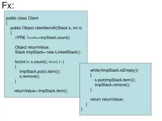
256 odd + 256 even channels F-Engine Fix 8_7 X0 X1 • Phase Switching • P, P2 Calculation + Quantization/Scaling + Accumulation X7 ? DPP F – engine : 4096 Channel • Phase Switching • Where? How: Input? • “Rate required 1.25 ms”? • Phase switching is difficult on FPGA. Dan suggests doing it before ADC, and then undoing it on FPGA. Nimish Sane, New Jersey Institute of Technology
F-Engine • No. channels • 4096 for now • At what point do we throw 100 MHz? (≈ 672 channels) • Generating the spectral kurtosis power and power-squared in the F-engine • P (32-bit): Data rate: 819200 bytes/sec • P2 (64-bit): Data rate: 1638400 bytes/sec • Total data rate per Roach board: 9830400 bytes/sec ≈ 78.6 Mbps • Use 100 Mbps link? Nimish Sane, New Jersey Institute of Technology
uv coverage showing the baseline lengths in nsec for a source at +30 declination Nimish Sane, New Jersey Institute of Technology
F-Engine • Amount of coarse delay needed • -5000 to 5000 ns (Since we can only introduce positive delays, the actual delays will be 0 to 10000 ns) • This should be possible. It may affect resource utilization, but should not be a constraint • “Correlatordoes all phase crrections such as fringe rotation, fine delay, as well as conversion from X, Y to R, L • How to do this? • Coarse delay on FPGA, fine delay off-line • ATA memo on fringe stopping after FFT • GMRT does fringe stopping + coarse delay + fine delay + (possibly) phase switching, but not at 600 MHz Nimish Sane, New Jersey Institute of Technology
F-Engine Nimish Sane, New Jersey Institute of Technology
F-Engine • Issue of channel-flattening gain compensation to keep the digitized signals in a 4-bit range • It is quite easy for the Sun to produce very narrow spectral features of high intensity • These features will put the affected channels out of range for 4-bit correlation --- large corrections in software. How? • Per-channel scaling • Required for P, P2, Correlation • How to determine the per-channel gain? • Transmit all gain values in the header? • 4-bit correlation: • Nothing special in CASPER tutorial. Using rounding and saturate while converting data to fewer bits (and clipping data out of range) Nimish Sane, New Jersey Institute of Technology
Header • FST • 40 bytes • Header length (1 byte) • Accumulation length (2 bytes) • Packet number within an accumulation (1 byte) • Accumulation number (4 bytes) • Delay0, Delay1, Delay2 (4 bytes each) • Gain ( 4 bytes) • FFT Shift (4 bytes) • Stokes coeff scaling, Kurtosis scaling factors (P, P2) (4 bytes each) • Additional delay3 • Per-channel “gain” or scaling factor? • SPEAD protocol • Seems what we want, but have not found its implementation • Documentation on Casper Wiki Nimish Sane, New Jersey Institute of Technology
X-Engine UFix M ? Fix N_3 ? (64) (960) X – Unit Each Roach board will have 1 X-unit, and each X-unit will handle 4096/8 = 512 frequency channels (256 even and 256 odd channels) No. of complex multipliers in each X-unit correlator block = No. of visibilities x No. of polarizations x Simultaneous even and odd channels per F-unit = 120 x 2 x 2 = 480 Nimish Sane, New Jersey Institute of Technology
X-Engine • F, X on FPGA • No GPU • Current state of art: • F and X engines on different boards • F + X on the same board: (1) Can we fit the design? (2) Can F + X work in tandem? • Use full-duplex bidirectional capacity of 10 GbE link: Send output of F – engine to a switch that will distribute it to X – engines (even if F and X are on the same board) Nimish Sane, New Jersey Institute of Technology
X-Engine • No. of F-engines per Roach board = 4 (2 antennas dual polarization) • Output of an F-engine: Complex (even and odd channels), each with 18-bit real and 18-bit imaginary; Output data of F-engines per Roach board per FPGA clock cycle = 72 x 4 bits • Total data rate out of F-engines per Roach board = 72 x 4 x 300 x 106 = 86.4 Gbps(for 300 MHz FPGA clock) • Data rate from F-Engine to 1 X-engine = 10.8 Gbps • Roach2 supports 8 x 10 GbE ports. So this will not be possible. • If we only transmit 3424 channels (~ 500 MHz band) to X-engine, then total data rate out of F-engines per Roach board = 86.4 x 109 x 1712 / 2048 = 72.225 Gbps • Data rate from F-Engine to 1 X-engine = 9.03 Gbps • Plus header information. • Should we employ scaling/quantization in F-engine and transmit just 8-bit complex number (4-bit real and imaginary) to X-engines? This will reduce data rates by a factor of 18x • For X – engine: (input) M = ? 36 or 8 • For X – engine: (output) N = ? • Accumulation length (for 20 ms, 300 MHz clock, 256 channels) = 23437 < 215 • N ≥ 19 • X-unit output data per integration = 480 x 2 x 256 x 19 bits = 4669440 bits • Total data rate at the output of X-unit per Roach board = 983040 x 50 = 233.472 Mbps (assuming integration time of 20 ms) Nimish Sane, New Jersey Institute of Technology
F and X-engine Connections • What happens when a signal exceeds the 4-bit quantization? • Data is lost. • Dale: We may be better off scaling for 3 bits and leaving at least 1 bit of headroom. At least the Van Vleck correction can apply to fewer bits, and while we lose efficiency we do not lose the data itself. • We may also need to figure out how to detect when channels are clipping • some sort of statistical measure: Gelu? Nimish Sane, New Jersey Institute of Technology
General Comments/Issues Synchronization with external clock “No need for solar or geometrical coordinates. Only delay (sum of delay center and geometric delay) and delay rate information is needed for corrections. What update rate is necessary?” (?) “Need to set sign convention in correlator to make u, v come out in standard way.” (?) Open question: “Should the subchannel have simple bandwidths (e.g. 0.5 MHz by setting clock speed appropriately)?” Nimish Sane, New Jersey Institute of Technology
References Nimish Sane, New Jersey Institute of Technology https://casper.berkeley.edu/wiki/ROACH2 P. McMahon, et al. “CASPER Memo 017: Packetized FX Correlator Architectures,” September 2007.