Download
1 / 19
190 likes | 366 Vues
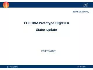
Objectives, strategy and present status of the prototype TBM program. Review of the TBM lab program Nov. 6 th , 2013 G. Riddone, BE-RF-PM. Important program developed in collaboration with several CERN groups. Content. Introduction CLIC Layout Module layout TBM LAB program

E N D
Objectives, strategyand presentstatus of the prototype TBM program Review of the TBM lab program Nov. 6th, 2013 G. Riddone, BE-RF-PM Important program developed in collaboration with several CERN groups.
Content • Introduction • CLIC Layout • Module layout • TBM LAB program • Objectives • Strategy • Status
CLIC Layout at 3 TeV Drive Beam Generation Complex Main Beam Generation Complex Main LINAC two-beam modules
Two-beam module layout A. Samoshkin CLIC at 3TeV (21460 modules) 142760 Accelerating structures 71380 PETS ~ 400000 RF components CLIC at 500 GeV (4232 modules) 26920 Accelerating structures 13460 PETS ~ 70000 RF components
TBM main types Standard Module (L = 2010 mm) DB (100 A) 4 PETS, 2 Quads with BPM Each PETS feeds 2 AS MB (1 A) 8 acc. structures MB filling factor: 91% CLIC Module Type o 73 % Module Type 1 3 % Module Type 3 9 % DB Module Type 2 12 % Module Type 4 3 % 1 to 4 pairs of AS replaced by MB Quadrupoles MB
Main requirements Main requirements Module design and integration coping with challenging requirements from different technical systems. Baseline solutions were defined for each technical system in the CDR
CLIC feasibility issues CLIC feasibility issues Demonstration of novel scheme of two beam acceleration in compact modules integrating all technical systems for RF production, beam measurement and acceleration including alignment, stabilisation and vacuum at their nominal parameters.
Two-beam acceleration validation 2009-2013 Two-beam test stand (PETS and ac. structures) Demonstration of the two-beam acceleration with one PETS and one accelerating structure at nominal parameters in CLEX 2011-2015 • Demonstration of the two-beam module design • This implies: • the assembly and integration of all components and technical systems, such as RF, magnet, vacuum, alignment and stabilization, in the very compact 2-m long two-beam module • validation of the thermal and mechanical module behavior TBM Lab Demonstration of the two-beam acceleration with two-beam modules in CLEX Address other feasibility issues in an integrated approach TBM CLEX
TBM Lab objectives • Integration of all technical systems • Validation of different types of girders and movers • Pre-alignment of girders/quadrupoles in the module environment, • Full metrology of the module components • Validation of interconnections and vacuum systems under different thermal loads • Stabilization of main beam quad in the module environment • Vibration study of all systems and identification of vibration sources • Measurement of resonant frequencies • Simulation of several thermal cycles and alignment verification • Transport of the module and alignment verification CLIC Two-Beam Module Type 0 in B169
TBM Lab overall status TM1 TM0#1 TM0#2 TM4 1) Under test 2) Under assembly and installation 3) Components under procurement and assembly 4) Last module – few components under procurements
TBM T1 in LAB *possibility to integrate a real SAS **DB and MB girders + V-shaped supports are fabricated; cradles fabrication is under way.
TBM T4 in LAB *DB girder + V-shaped supports are fabricated.
Test objectives TM01 • Understanding geometrical tolerances of assembled modules • Geometrical stability • Temperature • map in the module • variations with operating modes and environmental conditions (simulation of the real tunnel environment - air flow, ambient T) • time constants • Functionality of the technical systems: • cooling system • vacuum system • active alignment system • stabilisation system See next talks Dmitry Fabrizio Hélène Cédric Detailed reports available in EDMS: https://edms.cern.ch/nav/P:AB-011534:V0/P:AB-001829:V0/TAB3
Requirements for AS and PETS Turning – milling Several annealing steps (no burrs, no scratches) AS Disk PETS bar Dictated by beam physics and RF ultra high precision machining