Download
1 / 19
190 likes | 359 Vues
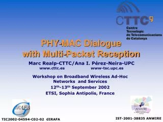
PHY-MAC Dialogue with Multi-Packet Reception. Marc Realp-CTTC/Ana I. Pérez-Neira-UPC www.cttc.es www-tsc.upc.es. Workshop on Broadband Wireless Ad-Hoc Networks and Services 12 th -13 th September 2002 ETSI, Sophia Antipolis, France. IST-2001-38835 ANWIRE.

E N D
PHY-MAC Dialogue with Multi-Packet Reception Marc Realp-CTTC/Ana I. Pérez-Neira-UPC www.cttc.es www-tsc.upc.es Workshop on Broadband Wireless Ad-Hoc Networks and Services 12th-13th September 2002 ETSI, Sophia Antipolis, France IST-2001-38835 ANWIRE TIC2002-04594-C02-02 GIRAFA
Contents • Motivation • Cross-Layer Design • MPR matrix. • PHY-MAC dialogue. • Parameters Exchange. • PHY level • Matched Filter. • Activity User Detection. • MAC level • Dynamic Queue Protocol-DQP. • Modified Dynamic Queue Protocol-MDQP. • Simulations • Conclusions & Further Work
Motivation • Motivation • Cross-Layer Design • PHY level • MAC level • Simulations • Conclusions & Further Work • In wireless systems a common channel is shared by many users. • Traditionally, information is lost when a collision occurs, i.e., when two or more packets are sent trough the channel. • Diversity at physical level allows more than one packet to be transmitted simultaneously. • Conventional MAC algorithms do not consider Multi-Packet Reception (MPR) capability. CROSS-LAYER DESIGN MAC fully exploits PHY reception capabilities.
MPR matrix • Motivation • Cross-Layer Design • PHY level • MAC level • Simulations • Conclusions & Further Work • The probability of a packet to be correctly received is: • Hence,
MPR matrix • Motivation • Cross-Layer Design • PHY level • MAC level • Simulations • Conclusions & Further Work • The MPR matrix is defined as: • Expected number of correctly received packets when n packets have been transmitted:
MAC Layer PHY Layer Modulation Scheme Bit Rate Scheduling Fairness Delay PER BER Power Tx/Rx Battery Life Error Correcting Code (Binomial) Traffic Modelling Throughput Diversity Transceiver Architecture Channel & Signal Estimation Number of Users ? ? QoS ? ? PHY-MAC Dialogue • Motivation • Cross-Layer Design • PHY level • MAC level • Simulations • Conclusions & Further Work • Cross-Layer design reduces PHY-MAC dialogue to a BER exchange. Should other parameters be considered in order to improve system performance?
Parameters Exchange • Motivation • Cross-Layer Design • PHY level • MAC level • Simulations • Conclusions & Further Work • Information flows between PHY and MAC levels: • BER is used for MPR computation. • Active Users used for MAC efficiency. • Access Set used for PHY efficiency. MAC BER ACT. US. ACC. SET PHY
PHY Level • CDMA System Model • Receiver Structure • Motivation • Cross-Layer Design • PHY level • MAC level • Simulations • Conclusions & Further Work Set of Active Users Detection of Active Users e(t)
: Indicator function that takes value 1 if the kth user is active and 0 otherwise e MF ||•||2 State Estimation Power detection Decision based on Traffic Information PHY Level • Motivation • Cross-Layer Design • PHY level • MAC level • Simulation • Conclusions & Further Work • Data Demodulator • Matched Filter • Active Users Detector
Dynamic Queue Protocol-DQP • Motivation • Cross-Layer Design • PHY level • MAC level • Simulations • Conclusions & Further Work • System with M users to transmit data to a central controller. • Time axis is divided into transmission periods (TP). • A TP ends when all packets generated in the previous TP are successfully transmitted. • The basic structure is a waiting queue where all users in the system are processed in groups of Access Set size. • Based on packet user probability in one TP (qi) and the MPR matrix, the size of the access set which contains users who can access the channel in the ith TP is chosen optimally. Transmit packets generated in (0,4] Transmit packets generated in (4,11] Transmit packets generated before 0 First TP L1=4 Second TP L2=7 Third TP L3=5
DQP MDQP Non-empty slot. Nodes 2 and 4 packets successfully received. Non-empty slot. Node 2 packet lost. Node 3 packet successfully received. Node 1 empty Non-empty slot. Nodes 2 and 4 packets successfully received. Node 5 empty. Non-empty slot. Node 3 packet successfully received. Node 2 packet lost. Empty slot 3 3 4 4 2 2 2 2 1 1 1 1 2 Access Set=3 2 2 2 4 5 3 4 3 5 4 5 4 5 5 Central controller do not know whether packets from nodes 1 and 5 have collided or the buffers of these nodeswere empty. Central controller determines that nodes 1 and 5 have empty buffers. Successfully received packet Packet waiting for transmission Packet Lost Empty buffer DQP Vs MDQP • Motivation • Cross-Layer Design • PHY level • MAC level • Simulations • Conclusions & Further Work • MDQP stands for Modified Dynamic Queue Protocol. • Central controller in DQP is capable to distinguish between: • Empty slots. • Successfully received packets in non-empty slots. • Central controller in MDQP is capable to distinguish between: • Empty slots. • Successfully received packets in non-empty slots. • Packets lost due to collision in non-empty slots. • Nodes with empty buffers in non-empty slots.
MDQP Optimal Access Set • Motivation • Cross-Layer Design • PHY level • MAC level • Simulations • Conclusions & Further Work • Ni is chosen in order to minimise the absorbing time of a finite state discrete Markov chain. • Each state (j,k) defines: • j=number of unprocessed users in one slot • k=number of packets sent in one slot C2,2 C2,0 C2,1 2,2 C1,0 1,1 C1,0 C1,1 2,1 0,0 1 C1,1 1,0 Number of Users(M)=2 Access Set (N)=2 1 2,0 1
Access Set Vs User Packet Probability • Motivation • Cross-Layer Design • PHY level • MAC level • Simulations • Conclusions & Further Work MDQP DQP Access Set User Packet Probability (qi) Packet Length (pl)=200bits Number of Correcting Errors(e)=2 Receiver type: Matched Filter Number of Users (M)=15 SNR=10 Spreading Gain (SG)=6
Throughput Vs User Packet Probability • Motivation • Cross-Layer Design • PHY level • MAC level • Simulations • Conclusions & Further Work M=10 M=15 Throughput M=5 MDQP DQP User Packet Probability (qi) Packet Length (pl)=200bits Number of Correcting Errors(e)=2 Receiver type: Matched Filter SNR=10 Spreading Gain (SG)=6
Packet Delay Vs User Packet Probability • Motivation • Cross-Layer Design • PHY level • MAC level • Simulations • Conclusions & Further Work M=15 M=10 Packet Delay M=5 MDQP DQP User Packet Probability (qi) Packet Length (pl)=200bits Number of Correcting Errors(e)=2 Receiver type: Matched Filter SNR=10 Spreading Gain (SG)=6
Conclusions • Motivation • Cross-Layer Design • PHY level • MAC level • Simulations • Conclusions &Further Work • Cross-Layer design concept. • New idea of PHY-MAC dialogue. • Number of active users used as an additional parameter exchange between layers. • Proposal of a centralised system • PHY layer with active users detector. • MAC layer with MDQP. • System improvements in terms of throughput and packet delay.
MPR matrix for Ad-Hoc Networks • Motivation • Cross-Layer Design • PHY level • MAC level • Simulations • Conclusions &Further Work • MPR must be modified considering communications in Ad-Hoc scenarios. • Communications are Half-Duplex. • A node can not receive a packet while is transmitting. • A node might successfully receive a packet not intended for it. • Packet might be lost due to collision of many packets. 3 1 5 2 Packet intended for that node 4 Packet not intended for that node
PHY-MAC Dialogue in the IEEE802.11b • Motivation • Cross-Layer Design • PHY level • MAC level • Simulations • Conclusions &Further Work • CSMA/CA is used. Medium is sensed by means of active user detection mechanism. • Medium is determined IDLE when Number of users sensed < Nopt for a period longer than DIFS. • After deferral, Back-off procedure adjusted depending on Number of users sensed. Contention Period (CP) DIFS PIFS SIFS Busy Medium (N. Users>=Nopt) Back-Off procedure
PHY-MAC Dialogue in the IEEE802.11b • Motivation • Cross-Layer Design • PHY level • MAC level • Simulations • Conclusions &Further Work • Analytical throughput expression • Nopt for throughput maximisation • Modifications on the current 802.11 standard. • Additional information flows: • PHY->MAC: Number of current active users. • MAC->PHY: Number of users (Nopt) to consider busy medium. • Additional field in Beacon frames or broadcast message to transmit Nopt. • Carrier sense mechanism modifications • User activity detection and MUD at PHY level. • Possible change in back-off procedure for better performance. • Simulations