Ground Based Observatories (GBO) System Design Overview Operational Status Lessons Learned
290 likes | 460 Vues
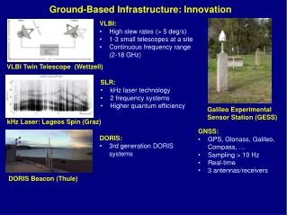
Ground Based Observatories (GBO) System Design Overview Operational Status Lessons Learned. S. E. Harris University of California - Berkeley. Internet. GBO Components. Iridium. All Sky Imager (ASI). GPS. Observatory Support Equipment (OSE) inside the “Hut” enclosure. Telesat Dish.

Ground Based Observatories (GBO) System Design Overview Operational Status Lessons Learned
E N D
Presentation Transcript
Ground Based Observatories (GBO) System Design OverviewOperational StatusLessons Learned S. E. Harris University of California - Berkeley
Internet GBO Components Iridium All Sky Imager (ASI) GPS Observatory Support Equipment (OSE) inside the “Hut” enclosure Telesat Dish Ground Magnetometer (GMAG) AC Power • Variations possible at some sites: • Existing magnetometer • “Hut” enclosure not needed • Existing Internet connection
All Sky Imager (ASI) • Main Components • Camera, Starlight Xpress, MX716 • Designed for amateur astronomy • CCD Format: Interline transfer, 376 x 290 pixels (binned), 8mm diag. • Cooled with TEC for reduced dark current • All Sky Lens • Telecentric design by Keo Consultants • Full hemisphere viewing, full resolution obtained 256 x 256 image • Environmental Enclosure with Sun Shade
ASI Unit Test Summary • Acceptance Tests: • FOV (>170°) • Exposure Time (duration at least 1 sec) • Spectral Response • Produce detectable response to source radiance < 10kR • Goal < 1kR • Passband 400 – 750nm • 1 sec exposure duration • Spatial Resolution (>250 pixel image diameter) • Verify point source response • Cadence (better than 10s) • Goal < 3s • Record dark and bias images (room temperature) • Pre-Shipment: • Focus adjustment and verification • Alignment verification (top of image relative to alignment datum) • Heater control functional test • Sun Shade solenoid functional test (#iterations: 360) • Internal mechanical inspection checklist (thm_gbo_116) • Final functional test and System Burn-in (duration: several days)
ASI Responsivity Testing • Data report: thm_gbo_118 • Recorded on all Imagers: • On Axis spectral response • Off Axis spectral response • Dark vs exposure time • Resolution
ASI Resolution Testing On-Axis 40º Off-Axis 80º Off-Axis
ASI Enclosure Design Acrylic Dome S.S. Enclosure Heaters Design: Allison Park Group, Inc.
Sun Shade • ASI must survive non-operating exposure to daytime sun • CCD is Sony ICX249AL • Plastic “microlens” on each pixel, transmission reduction w/ exposure to UV • All Sky Lens uses Peleng Fisheye f/3.5 • A/R coating exhibited discoloration after one summer in ATHA • Solenoid drive actuates to close shade • Falls open when solenoid power is removed
ASI Enclosure Performance ASI installed at Ft. Yukon, AK • Dome: • Generally stays clear of snow without intervention • Some ice buildup on flange • Heating: • Maintains 60° T using about 50W avg. heat power • Total heating power available is 240W (60W in dome)
Ground Magnetometer • GPS Receiver (included at all GBO sites) Antenna and Electronics Integrated into one package NTP compatible (1msec time accuracy) • Fluxgate Magnetometer (sensor shown below) • ±72KnT dynamic range @ 0.01nT Resolution (~23 bits) Offset DAC system for 256 possible ranges per axis 2 Vectors per second data rate Low Power < 4W USB interface for data retrieval and firmware upload
GMAG Installation • Fluxgate Magnetometer Installed at Athabasca
28” OSE Layout (1) Rack Mount Shipping Case (12U) System Computer GMAG Interface Electronics APS Serial Switch Swappable Hard Drive (2 ea) Iridium modem UPS
OSE Layout (2) Power Control Unit CR10X Datalogger UPS ASI Power Supply CR10X Battery
Power Control Unit (PCU) • PCU Features • CR10X Datalogger is the environment controller for GBO • Extended temperature range (-55º to +85ºC) • Always operating and remotely accessible (via Iridium) • Low power consumption (battery can operate it for months) • Simple programming and data logging capability • Provides room temperature environment inside OSE and ASI • Enables use of standard commercial computers, hard drives, etc. • Implements graceful shutdown of system in either event of: • Loss of Power • Loss of Temperature (either too high, or too low) • CR10X is the analog & digital I/O peripheral for System Computer • Provides “watchdog” function for System Computer (PC)
OSE Heating / Cooling Devices Solid State Air Conditioner 163W Capacity 120VAC Power Small Space Heaters 175W, 120VAC, 2 ea
“Hut” Enclosure “A Box within a Box” Internal Rack Mount Case for Equipment (Doubles as Shipping Case) External Insulated Environmental Enclosure
Hut Performance • No heating in Hut required down to –40ºC GBO#10, Ft. Smith • Cooling required above –5ºC GBO#10, Ft. Smith
Internet Instrument Data Flow ASI System Computer Hot Swap Hard Drive(s) GMAG Telesat Modem GPS USB Serial I/O 10/100 Base T
Status of Operations • Number of GBOs Deployed: 11 • Installation and logistics can be difficult • Monitoring and maintaining is harder • Some operational hazards that we’ve survived so far: • Cold • e.g. door to the shack stuck open • Hot • e.g. stuck thermostat in the shack • Power • generally it’s been reliable, but outages are a fact of life • Inaccessibility • Ekati and Inuvik • RF Interference (More on this later) • Internet connection outages • data back up is working fine • Software issues • system processes can hang up (USB interfaces, NTP daemon) • periodically we need to reboot the system • Non-responsive custodian
System Uptime • Initial analysis, 8 of 10 stations analyzed • Based on availability of CR10X records logged on site • At each station, number of records is averaging 97.5% • Of 288 records maximum per day • Indicates the systems are up and running normally most of the time
Learning and Improving • System issues are addressed in Problem Reports • PFRs describe problem and corrective action • We track PFRs for each station • Leaves a paper trail of changes for each site • A copy also is attached to site log on ‘wiki’
Lessons Learned - Prototype • Ice buildup on ASI dome • Added dome heaters • Insulation outgassing in ASI • Changed material to foil-faced air pillow
Lessons Learned (1) ASI Power Diagram
Lessons Learned (2) USB Disconnect Device Prototype Modified USB Board
Lessons Learned (3) Overheated PC Boardcourtesy of Mikko Syrjasuo Modified Starlight Brick
Lessons Learned (4) ASI Data Interface Diagram