Overview of Error Correction Coding in Multimedia Security
Explore the challenges of multi-symbol message encoding and the concept of error correction codes in multimedia security. Error Correction Codes (ECC) improve data integrity by defining code words and implementing decoders to correct errors. Learn about various ECC types such as Hamming Codes, Algebraic Codes, and Statistical Codes for different error types. Discover how ECC enhances data reliability by increasing symbol sequence lengths or expanding alphabets.

Overview of Error Correction Coding in Multimedia Security
E N D
Presentation Transcript
Error Correction Coding Multimedia Security
Outline • Part 1.The Problem with Simple Multi-symbol Message • Part 2.The Idea of Error Correction Codes
In direct message coding, we can choose any set of message marks we wish. Thus, we can ensure that the angle between any pair of message marks is maximal. • In any multi-symbol system, however, code separation depends on the methods used for source coding and modulation.
If every possible symbol sequence of a given length is used to represent a message, using CDM, some of the resulting vectors will have poor code separation. • This is because there is a lower limit on the inner product, and hence, an upper limit on the angle between the resulting message marks.
For example,consider a system with an alphabet size |A| = 4 and message length L = 3.Letbe the message mark embedded in a work to represent the symbol sequence 3,1,2.
Now examine the inner product between this message mark and the message mark that encodes the sequence 3,1,4 (which differs only in the last symbol); namely,
The inner product between these two vectors is given by (because all marks for one location are orthogonal to all marks for any other location)
Suppose all the marks are normalized to have unit variance. This means and both equal N (the dimensionality of marking space), while is bounded by –N . • Thus, , and the inner product between the two closest encoded messagescannot possibly be lower than this.
In general, the smallest possible inner product between two message marks that differ in h symbols is N(L - 2h).
Thus, as L increases, the message marks of the closest pair become progressively more similar.=> the code separation is getting poor as L increases.=> false alarm rate ↗↗
The above problem can be solved by defining a source coding system in which NOT every possible sequence of symbols corresponds to a message!
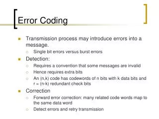
Sequences that correspond to messages are referred to as codewords. Sequences that do not correspond to messages are interpreted as corrupted code words.
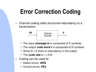
By defining the mapping between messages and codewords in an appropriate way, it is possible to build decoders that can identify the codeword closest to a given corrupted sequence (i.e., decoders that correct errors). • Such a system is an Error Correction Code, or ECC.
ECC ’s are typically implemented by increasing the lengths of symbol sequences.
For example,if we have 16 possible messages, we could represent the message with a sequence of 4 bits.The ECC encoder, then, takes this sequence as input, and output a longer sequence, say 7 bit. Of all the 27 = 128 possible 7-bit words, only 16 would be code words.
The set of code words can be defined in such a way that if we start with one code word, we have to flip at least 3 bits to obtain a code word that encodes a different message.
When presented with a corrupted sequence, the decoder would look for the code word that differs from it in the fewest number of bits. If only one bit has been flipped between encoding and decoding, the system will still yield the correct message.
t t ci cj
If we have a 7-bit code (L = 7) encoding 4-bit messages and ensuring that the code words of every pair differ in at least three bits (h = 3) , the maximum inner product between any two code words will beN(L - 2h) = N(7 - 2x3) = N.
This is better than the performance we would get without error correction, where messages are coded with only 4 bits (L = 4) and two messages can differ in as few as one bit (h = 1) .
In this case, the maximum inner product would be N(L- 2h) = N(4 - 2) = 2N. • Of course, one can increase the size of the alphabet, rather than the length of the sequences.
There are many ECC ‘s available. • (7;4) Hamming Code : single bit error correctable. • Algebraic Codes : BCH, RS • Statistical Codes / Convolutional Codes : Trellis Code, Turbo Codes
Different codes are suitable for different types of errors. • Random errors → Hamming Codes • Burst errors → BCH Codes(errors in groups of consecutive symbols)
Since all code words are ultimately modulated, we can view all codes as convenient methods of generating well-separated message marks.
Example: Trellis Codes and Viterbi Decoding Encoding: • The encoder can be implemented as a finite-state-machine, as illustrated in Fig. 4.8 . • The machine begins in state A and processes the bits of the input sequence one at a time. As it processes each input bit, it outputs 4 bits and changes state.
Example: Trellis Codes and Viterbi Decoding • If the input bit is a ‘0’, it traverses the light arc coming from the current state and outputs the 4 bits with which that arc is labeled. • If the input bit is a ‘1’, it traverses the dark arc and outputs that arc’s 4-bit label. Thus, a 4-bit message will be transformed into a 16-bit code word after encoding.
Example: Trellis Codes and Viterbi Decoding • e.g.the 4-bit sequence the 16-bits code word (1,0,1,0) (0001,1100,1111,1110)
Example: Trellis Codes and Viterbi Decoding • Note that each bit of the message effects not only the 4-bit used to encode it (behaving as input) but also the encoding of several subsequent bits (behaving as state). • Thus, the subsequent bits contain redundant information about earlier bits.
Example: Trellis Codes and Viterbi Decoding • Fig. 4.9 shows an alternative representation of the code, in a diagram called a trellis. • Here, we have 8(L + 1) states, where L is the length of the input sequence.
Example: Trellis Codes and Viterbi Decoding • Each row of states corresponds to one state in Fig. 4.8 at different times. A0 (in Fig. 4.9) → state A (in Fig. 4.8) at the beginning of the encoding. A1 (in Fig. 4.9) → state A (in Fig. 4.8) after the 1st input bit has been processed. • Each possible code word corresponds to a path through this trellis starting at A0 !!
Example: Trellis Codes and Viterbi Decoding • We can replace the 4-bit arc labels with symbols drawn from a 16-symbol alphabet.=> We can assign a unique reference mark to each arc in the trellis of Fig. 4.9 (one each for each of the 16 symbols in each of the L sequence locations).
Example: Trellis Codes and Viterbi Decoding => The message mark resulting from a given code word, then, is simply the sum of the reference marks for the arcs along the path that corresponds to that code word. This is known as trellis-coded modulation.
Example: Trellis Codes and Viterbi Decoding Decoding: • Decoding a trellis-coded message is a matter of finding the most likely path through the trellis.
Example: Trellis Codes and Viterbi Decoding • The most likely path is the one that leads to the highest linear correlation or inner product between the received vector and the message vector for that path. • This can be found efficiently using an algorithm known as Viterbi decoder.
Example: Trellis Codes and Viterbi Decoding • The Viterbi algorithm relies on the fact that the most likely path through each node in the trellis always includes the most likely path up to that node. • Thus, once we find the most likely path from A0 to some node further into the trellis, we can forget about all the other possible paths from A0 to that node.
Example: Trellis Codes and Viterbi Decoding • The algorithm proceeds by traversing the trellis from left to right. • For each of the 8 states in the columns of the trellis, it keeps track of the most likely path so far from A0 to that state, and the total inner product between the received vector and the reference marks along the path.
Example: Trellis Codes and Viterbi Decoding • In each iteration, it updates these paths and products. When it reaches the end of the trellis (i.e., the end of the coded message), it has found the most likely path from A0 to each of the 8 final states. • It is then a simple matter to decide which of the resulting 8 paths is most likely.
Example: Trellis Codes and Viterbi Decoding Notations: • is the received vector being decoded. • is the reference mark associated with the arc in the trellis from state i to the state j . For example, is the reference mark associated with the arc from state A0 to B1 .
Example: Trellis Codes and Viterbi Decoding Notations: • P[A,…,H] is an array of eight paths.At any given time, P[i] is the most likely path that leads up to state i in the current column. For example, when processing column 3, P[C] is the most likely path that leads up to state C3 .
Example: Trellis Codes and Viterbi Decoding Notations: • Z[A,…,H] is an array of eight inner products.At any given time, Z[i] is the total product between the received vector, , and the reference marks for path P[i].
Example: Trellis Codes and Viterbi Decoding Viterbi Algorithm: • At the beginning of the algorithm, P[A,…,H] are initialized to the null path, and Z[A,…,H] are initialized to 0.
Example: Trellis Codes and Viterbi Decoding Viterbi Algorithm: • In the first iteration, we compute the inner product between the received vector and the 16 reference marks associated with the arcs that go from states in column 0 to states in column 1.
Example: Trellis Codes and Viterbi Decoding Viterbi Algorithm: • To find the total product between the received vector and a path from a state in column 0 to a state in column 1, we add the product with the corresponding arc to the value in Z that corresponds to the column 0 state.
Example: Trellis Codes and Viterbi Decoding Viterbi Algorithm: • For example,the inner product for the path from A0 to B1 is just Z[A] + . Similarly, the product for the path from E0 to B1 is Z[E] + .
Example: Trellis Codes and Viterbi Decoding Viterbi Algorithm: • By comparing the inner products for the two paths that lead up to a state in column 1, we can decide which path to that state is most likely, and update P and Z accordingly.
Example: Trellis Codes and Viterbi Decoding Viterbi Algorithm: • For example, ifZ[A] + > Z[E] + than we would updateZ[B] ← Z[A] + P[B] ← P[A]; concatenated with the arc from A0 to B1.
Example: Trellis Codes and Viterbi Decoding Viterbi Algorithm: • This process is repeated L times, until we reach the end of the trellis. At that point, we identify the most likely path by finding the highest value in Z. • The path can then be converted into a decoded message.
Example: Trellis Codes and Viterbi Decoding Viterbi Algorithm: • The ensure that the most likely path always starts at A0 , we can modify this algorithm by initializing only Z[A] to 0 at the beginning.