Download
1 / 22
220 likes | 244 Vues
Explore the Chongo hardware building blocks including PC subsystem and Codec Module features. Learn about interfaces, components, and functionality provided by the hardware setup.

E N D
Prepared by Merlin Miller, Dave Jordahl, John Ciardi, March 2005 ChongoService TrainingHardware Overview
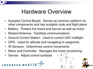
Chongo Building Blocks • PC Subsystem • Runs system and application software • USB, Firewire, DVD-ROM, RS422, and Ethernet interfaces • Disk Interface • PCI Bus interface to Codec Module • USB interface to Front Panel Module • Disk Array • 2 SATA drives in RAID0 array • Codec Module • Real-time control processor • MPEG SD encoder • 2 MPEG SD/HD Decoders • Audio DSP • Video and Audio I/O interfaces • Front Panel • WinCE Processor • TFT Display, TouchScreen, Keys, Knob Interface, LEDs
PC Subsystem • The PC subsystem runs application software running on top of a embedded WindowXP OS. This subsystem includes the following components: • Mechanical Chassis • Intel D865GLC microATX motherboard • 3.0GHz Pentium 4 processor • 512 MB DDR memory (2 DIM modules- separate memory busses) • 1 IDE port for interfacing to removable media drive (DVD-ROM/CD-ROM) • 1 10/100/1000BT Ethernet port • 4 rear panel/1 front panel accessible USB2.0 ports • 1 rear panel/1 front panel accessible ( front shared with second rear panel connector) Firewire IEEE1394A ports • 2 SATA ports for interfacing to internal media drives • 3 RS422 ports with SMPTE pinout (interfaced through internal USB connection) • PS2 keyboard and mouse ports • VGA display interface
Disk Array • 2 - 73GByte 10K RPM SATA Drives • Partioned into 3 Volumes • System Volume (C:) – 4GBytes on Physical Drive 0 • OS Swap and Media Database Volume (D:) – 4GBytes on Physical Drive 1 • Media Volume (V:) – 134GBytes striped across Drive 0 and 1
Front Panel • Front Panel System • Provides an intelligent interface that can operate the system without plugging in external monitor, keyboard, or mouse • FPS Components • Embedded Sharp ARM microprocessor with 16MBytes flash memory and 64MBytes SD-RAM • Runs WinCE operating system • 320x240 Pixel TFT Display • Integrated TouchScreen • Function and transport keys • Interface to intelligent knob • USB interface to PC Subsystem • 5V Power for FP circuits
Front Panel Intelligent Knob • Immersion Encoder • Rotary Encoder • Function depends on current Front Panel Application • Provides programmable stops and detents • Provides push-button functionality • Serial interface to Front Panel processor • 5V supply from Front Panel board
Codec Subsystem • The CODEC subsystem runs on a real time processor and includes all video based I/O processing. This subsystem includes the following components: • Real Time Processor: Intel Xscale • Video I/O • Audio I/O • LTC I/O • Genlock
Codec Subsystem RTP Section • Intel Xscale real time processor • Support PLD • PCI Bridge • JTAG Interface • I2C serial interface • Flash boot ROM • UART debug connector
Codec Subsystem Video I/O Recorder Section • Input is SDI, Analog composite, or Analog component • SDI Receiver integrated in FPGA • Composite and Component input using ADV7183B • LSI DVX MPEG encoder the same as M-Series
Codec Subsystem Video I/O Player Section • Output Mpeg decoder- Zoran TL955 • Component output directly from TL955 • DVI output from TL955 with TFP410 driver • SDI Transmitter integrated in FPGA • Composite output from ADV7191A same as M-Series • S-video output from ADV7191A extra ports
Codec Subsystem Audio I/O Section • Audio subsection similar to M-series • TI DSP processor for audio input and output processing • Digital I/O meeting SPDIF format, similar to AES format but different levels • Analog I/O with differential input and output • Front Panel Headphone driver
Codec Subsystem LTC I/O Section • LTC function implemented in FPGA • External LTC driver and receiver circuitry
Codec Subsystem Genlock Section • Provides reference video and audio clocks • Locks system clocks to input reference (PAL or NTSC)
RISER BOARD • RISER Board • Connects PCI bus and power from PC subsystem to CODEC board • General Purpose Interface connector and circuitry driven by Codec • Components • PCI connectors • GPI connector, drivers and receivers
XLR Breakout BOARD • XLR Breakout Board • Analog audio input connector for left and right channel recorder • Analog audio output connectors, 2 sets for player 1 and player 2 • Passive