Mobile Phone
Tanta University Faculty Of Engineering Electronics & Electrical Communication Department Challenger 8 Team. Mobile Phone. Signal Booster. Team Members . 1 . Mohammad Ashraf El- Sharkawy ( Leader ) 2. Al- Shaimaa Ibrahim El- Shenawy ( Manager )


Mobile Phone
E N D
Presentation Transcript
Tanta University Faculty Of Engineering Electronics & Electrical Communication Department Challenger 8 Team Mobile Phone Signal Booster
Team Members 1. Mohammad Ashraf El- Sharkawy ( Leader ) 2. Al- Shaimaa Ibrahim El- Shenawy ( Manager ) 3. Mohammad Mahrous Abd-Allah ( Presenter ) 4. Ola Mostafa Abu El-Naga ( Contact Person ) 5. Hanan Mohammad Abd AL- Galil ( Moderator ) 6. Heba Taha Ahmed Arafat ( Treasurer ) 7. Mohammad Abd El-Hakim Youssof ( member ) 8. Asmaa Ali mohammad ( Member )
Here’s the solution Signal Booster
Introduction Brief preview about GSM Technical parts & Implementation Market research conclusion
Users Of Signal Booster….. • 1- For people who are located in remote places and suffer from weak signal. • 2- It is very useful in cities, where in spite of full coverage there are places with no or poor signals. • 3-Simply plug our Signal Booster and you'll be astonished by the results.
Signal Booster Components: 1- Outdoor Antenna: 2- Base Unit: 3- Indoor Antenna:
Advantages • Increase indoor cell coverage up to 100 . • No more hanging out of the window to get a signal. • Unique in Egyptian market. • Very easy to install by the user. • Increase employee productivity. • Small size with special and distinct shape. • Improve battery life of your phone.
Introduction Brief preview about GSM Technical parts & Implementation Market research conclusion
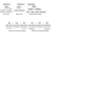
Block Diagram Power supply & Charge Battery IR System Outdoor antenna Indoor antenna [Downlink] Power amplifier Preamplifier AGC Outdoor antenna Indoor antenna [Uplink] Power amplifier BPF Preamplifier AGC
Power Supply Power supply & Charge Battery IR receiver Outdoor antenna Indoor antenna [Downlink] Power amplifier Preamplifier AGC Outdoor antenna Indoor antenna [Uplink] Power amplifier BPF Preamplifier AGC
Remote Control: • It’s a component of an electronic devices, used for operating the device wirelessly from a short line- of- sight distance. Remote control is consumer IR device.
Outdoor Ant. Power supply & Charge Battery IR receiver Outdoor antenna Indoor antenna [Downlink] Power amplifier Preamplifier AGC Outdoor antenna Indoor antenna [Uplink] Power amplifier BPF Preamplifier AGC
Advantages: • Obtain different types from polarization linear, circular or elliptical. • Operate in HF, VHF and UHF. • Considered as a broadband antenna. • Asimple way of obtaining high-gain. • Dimensions of the helix are small compared with the wavelength. • The antenna field is maximum in a plane normal to the helix axis and minimum along its axis. MODES OF OPERATIONS: NORMAL MODE:
2) Axial Mode: • The helix dimensions are at or above the wavelength of operation. • Commonly employed only at frequencies ranging from VHF up to microwave. • Produces a true and consistent circular polarization. • Provides better gain and high bandwidth ratio as compared to the normal mode of operation. • Installed on communication satellites and space vehicles as well as on earth station.
Helical Software Design: Output for software: Input for software: • Frequency =900MHZ. • Wavelength = 0.33m. • NO. of turns =5 turns. • Pitch angle = 14 degrees.
Matching: • Ensures that the max Power is transferred from the outdoor antenna to the base unit through coaxial cable. • Reduce the impedance of the outdoor antenna using:
Coaxial Cable: It's electrical cable used to carry RF signal. ADVANTAGES: • Large bandwidth than twisted pair. • High data rate. • High immunity to interference.
Application: For high frequency • Connecting TX and Rx with their antennas. • Local Area Network. For low frequency • Long distance telephone transmission. • F type connector : • Inexpensive. • 75Ω impedance. Connectors:
PreAmplifier Power supply & Charge Battery IR receiver Outdoor antenna Indoor antenna [Downlink] Power amplifier Preamplifier AGC Outdoor antenna Indoor antenna [Uplink] Power amplifier BPF Preamplifier AGC
Preamplifiers: • BGA 2003 (Silicon Amplifier): In general, the function of a preamp is to amplify a low-level signal to line-level. DESCRIPTION: Silicon amplifier consisting of an NPN double poly silicon transistor with integrated biasing for low voltage applications in a plastic.
Applications: • Wideband applications, e.g. analog and digital cellular Telephones. • High frequency oscillators. • Low noise amplifiers. FEATURES: • Low current. • Very high power gain. • Low noise figure. • Control pin for adjustment bias current. • Supply and RF output pin combined.
AGC & P. Amp. Power supply & Charge Battery IR receiver Outdoor antenna Indoor antenna [Downlink] Power amplifier Preamplifier AGC Outdoor antenna Indoor antenna [Uplink] Power amplifier BPF Preamplifier AGC
Objectives Of AGC: • Prevent intermodulation in base station receivers . • Prevent interference with other mobile phones using the same booster. • Minimize power consumption. • Using the minimum power necessary for reliable communication with the selected base station, based on distance.
PAC Loop Components: 1) Power Amplifier: • ALM-31122 • Fully matched ,input and output with 75 ohm. • 16.5 dB gain. • 5v supply. • Low noise figure. • Gain controlled.
2) Coupler • It’s used for the connection between PA o/p and the RF detector i/P. • The amount of coupling also defines the amount of feedback gain. • Converts the PA output voltage into a DC voltage used for comparison with the DSP value (vref). • HSMS-2825 schotty diode. 3) RF detector
4) Summer Circuit: V dsp Difference Amplifier Integrator Offset PA Control + + - Offset value Detector o/p
4.1) Difference amplifier • Error signal computation can be done using a difference amplifier. • V det=detector o/p • Vdsp=desired signal power level
4.2) Integrator • Difference amplifier. Combined with the integrator into one operational amplifier, the Differential Integrator block.
4.3) Offset • 2.8 V TX Enable signals produces the offset voltage. • The PA control voltage is the sum of the integrator output and the desired offset. • The loop is considered closed once the PA reaches threshold.
Indoor Ant. Power supply & Charge Battery IR receiver Outdoor antenna Indoor antenna [Downlink] Power amplifier Preamplifier AGC Outdoor antenna Indoor antenna [Uplink] Power amplifier BPF Preamplifier AGC
Indoor Antenna: • Omni directional antenna is used as indoor antenna. • It's antenna that radiates equally in all directions. • The only three dimensional Omni directional antenna is the unity gain isotropic antenna. Omni Antenna (100709):
Features: • Small and lightweight. • No tuning components. Electrical: • Frequency range: 880-960MHZ. • Polarization linear. • Feed point impedance 75 ohms. Mechanical: • Size: 37.59 x 11.94 x 2.77 mm. • Weight less than 2.5 g. • Mounting: surface mounted technology.
Typical Band: Typical Pattern:
PreAmplifier: Power supply & Charge Battery IR receiver Outdoor antenna Indoor antenna [Downlink] Power amplifier Preamplifier AGC Outdoor antenna Indoor antenna [Uplink] Power amplifier BPF Preamplifier AGC