Chapter 2: AC to DC Conversion (Rectifiers)
Chapter 2: AC to DC Conversion (Rectifiers). Rectifiers. Bridge rectifier. Overview. • Single-phase, Half Wave Rectifier – Uncontrolled : R, R-L – Controlled : R, R-L load – Free wheeling diode • Single-phase, Full Wave Rectifier – Uncontrolled : R, R-L load,


Chapter 2: AC to DC Conversion (Rectifiers)
E N D
Presentation Transcript
Chapter 2: AC to DC Conversion (Rectifiers)
Rectifiers Bridge rectifier
Overview • • Single-phase, Half Wave Rectifier • – Uncontrolled : R, R-L • – Controlled : R, R-L load • – Free wheeling diode • • Single-phase, Full Wave Rectifier • – Uncontrolled : R, R-L load, • – Controlled : R, R-L load • – Continuous and Discontinuous Current-Mode • • Three-phase Rectifier • – Uncontrolled • – Controlled
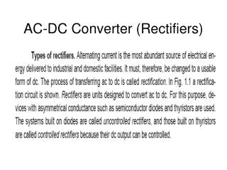
Rectifiers DEFINITION: Converting AC (from mains or other AC source) to DC power by using power diodes or by controlling the firing angles of thyristors/controllable switches. Basic block diagram • Input can be single or multi-phase (e.g. 3-phase). • Output can be made fixed or variable • Applications: DC welder, DC motor drive, Battery charger, DC power supply, HVDC
Single-phase, Half-Wave, R - load Example Given the supply voltage v = 120 Vrms, 60 Hz. Determines: a) The average load voltage and current b) The load voltage in r.m.s. c) The average power absorbed by the load, RL d) The power factor of the circuit Answer a) 54 V & 10.8 A, b) 84.9 V, c) 1440 W, d) 0.707
Example Solution
R-L Waveform vL is negative because the current is decreasing, i.e :
Extinction Angle • Note that the diode remains in forward biased longer than πradians (although the source is negative during that duration). • The point when current reaches zero is when diode turns OFF. • This point is known as the extinction angle, β.
Example Given Vm= 100 V , ω = 377 rads-1. Determine: a) An expression for current i and the extinction angle b) The average current c) The r.m.s. current d) The power absorbed by RL e) The power factor of the circuit Answer a) 0.936 sin(ωt - 0.361) + 0.331e - ωt/ 0.377, β= 201o(3.5 rad) b) 0.308 A, c) 0.474 A, d) 22.4 W, e) 0.67
Example 1. A half wave controlled rectifier has a source of 120V RMS at 60 Hz. R = 20 ohm, L= 0.04 H, and the delay angle is 45 degrees. Determine: (a) the expression for current i(ωt), (b) average current, (c) the power absorbed by the load. 2. Design a circuit to produce an average voltage of 40V across a 100 ohm load from a 120 VRMS, 60 Hz supply. Determine the power factor absorbed by the resistance.
Freewheeling diode (FWD) • Note that for single-phase, half wave rectifier with R-L load, the load (output) current is NOT continuous. (Bad current) • A FWD (sometimes known as commutation diode) can be placed as shown below to make it continuous
Operation of FWD • Note that both D1 and D2 cannot be turned on at the same time. • For a positive cycle voltage source, – D1 is on, D2 is off – The equivalent circuit is shown in Figure (b) – The voltage across the R-L load is the same as the source voltage. • For a negative cycle voltage source, – D1 is off, D2 is on – The equivalent circuit is shown in Figure (c) – The voltage across the R-L load is zero. – However, the inductor contains energy from positive cycle. The load current still circulates through the R-L path. – But in contrast with the normal half wave rectifier, the circuit in Figure (c) does not consist of supply voltage in its loop. – Hence the “negative part” of vo as shown in the normal half-wave disappear.
FWD- Continuous load current • The inclusion of FWD results in continuous load current (good current), as shown below. • Note also the output voltage has no negative part (prevent output voltage reversal). i.e. improve DC output voltage. • Transfer load current from main rectifier (allow rectifier regains its blocking state)
Why single-phase full-wave ? • To produce purely DC (less ripple) voltage or current • Suitable for high power application • Average current in the AC source is zero, thus avoiding problem associated with non-zero average source current especially in transformer
Full Wave Rectifier • Center-tapped (CT) rectifier requires center-tap transformer. Full Bridge (FB) does not. • CT: 2 diodes • FB: 4 diodes. Hence, CT experienced only one diode volt-drop per half-cycle • Conduction losses for CT is half. • Diodes ratings for CT is twice the FB.
Full Wave Bridge, R-L load Positive Half-Cycle Negative Half-Cycle
Example Given a bridge rectifier has an AC source Vm= 100 V at 50 Hz, and R-L load with R = 100 Ω, L = 10 mH i) determine the average current in the load ii) determine the first two higher order harmonics of the load current iii) determine the power absorbed by the load
To improve Vo, insert diode FWD across load
Discontinuous Mode Analysis similar to controlled half wave with R -L load:
Waveform – Continuous R – L Load ( L >> R )
Waveform – Continuous R – L Load ( L >> R ) Effect of inserting FWD
Single-phase diode groups • In the top group (D1, D3), the cathodes (-) of the two diodes are at a common potential. Therefore, the diode with its anode (+) at the highest potential will conduct (carry) id. • For example, when vs is ( +), D1 conducts id and D3 reverses (by taking loop around vs, D1 and D3). When vs is (-), D3 conducts, D1 reverses. • In the bottom group, the anodes of the two diodes are at common potential. Therefore the diode with its cathode at the lowest potential conducts id. • For example, when vs (+), D2 carry id. D4 reverses. When vs is (-), D4 carry id. D2 reverses.