Understanding Control Units and Algorithmic State Machines
610 likes | 710 Vues
Learn about control units in CPUs, ASM charts, and serial transmitters. Explore the design processes and components of control units and ASM charts to enhance your hardware understanding.

Understanding Control Units and Algorithmic State Machines
E N D
Presentation Transcript
Control Unit • An Instruction performs a well defined task such as adding a number in memory to a number in register file in CPU Example: ADD M(R1), R2, R3 which might mean : add the contents of memory location M(R1) to the contents of register R2 and leave the result in R3 • Requires a sequence of microoperations to bring the memory contents, to read the R2, to add, to write the result back in R3
Control Unit • The whole process requires a sequencing of microoperation control signals • Will depend on the instruction • Sequencing is done by the control unit • At each clock pulse, a different number of control signals become high. • The control signal coming out of the control unit is called a ‘control word’
Control Unit • There are 2 types of control units: • Hard wired- All circuits are sequential circuits and fixed • Microprogrammed: The control words are stored in a memory called ‘Control Memory’ • How do we design a hard-wired control unit?
Control Unit • Control units are just sequential circuits • Even a small CU can have many states and inputs • Classical sequential circuit design won’t work • Too many variables • Extremely difficult to modify • Therefore most control unit designs are based on some other sequential circuit architecture
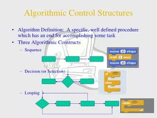
Algorithmic State Machines • One way of improving the level of understanding is to use ASM Charts • Algorithmic State Machine (ASM) • ASM charts look something like a software flow diagram • ASM chart is still basically a state diagram • Will be used to solve problems that will take a sequence , maybe a loop of microoperations in hardware • That’s why they are called Algorithmic State Machines
ASM • An ‘algorithm’ like sequence: t1.P: R0 R1 t2.Q: R2 M(R1) t3.T: R0 R1+R2 • A hardware Algorithm: Register transfers, microops and related control signals to realize a given task • ASM: representation of a hardware algorithm in a form of a flowchart
An example of an ASM: Multiplier An ‘ASM block’ is a state box and remaining boxes
ASM Chart Elements • ASM Charts are composed of ASM Blocks • An ASM block is composed of • One and only one state box • Optional decision boxes • Optional conditional output boxes • Each ASM block has a single entry • Connected to the state box • Multiple outputs are allowed (decisions) • Some outputs may be conditional (Mealy) • All transfers in an ASM block are performed in a common clock cycle.
ASM State Box Moore outputs go here
ASM Decision Box From ASM State Box Condition false path Condition true path c) ASM scalar decision box
ASM Conditional Output Box Mealy outputs go here
ASM Vector Decision Box Entry n-bit Condition Exit 0 Exit 1 Exit 2n-1 e) ASM vector decision box
Example:Serial Transmitter • Serial transmitter circuit is basically the same as the serial port output of your PC • Sends data to receiver by parallel to serial conversion (5 to 8 bits per transmission) • Extra information is transmitted so receiver knows where the data starts and ends • Odd or even parity can also be included for error detection
Serial Transmitter Block Diagram SERIAL TRANSMITTER 8 DATA SO 2 LS NS PE PS DONE GO CLK
Serial Transmitter Control / Protocol LS 00 01 10 11 Definition 5 bits 6 bits 7 bits 8 bits NS 0 1 Definition 1 stop bit 2 stop bits PE 0 1 Definition no parity parity bit PS 0 1 Definition even parity odd parity Data Bits (5 to 8), LSB first MARK SPACE Start Bit Parity Bit Stop Bit (1 or 2)
Serial Transmitter RTL MARK: SO ← ‘1’ SPACE: SO ← ‘0’, SR ← DATA, P ← PS DOUT: SO ← SR(0), SR ← shr(SR), P ← P O SR(0) POUT: SO ← P
Serial Transmitter Control • The serial transmitter CU must provide the proper sequence of control signals to the datapath • Controls are MARK, SPACE, DOUT, POUT • The sequence is conditional on the number of data bits, parity enable, and # stop bits • The GO input signals when to start operation • This gives us a total of 5 inputs
Serial Xmit State Diagram Initial Control Unit State Diagram ___ GO RST IDLE ------- MARK, DONE INIT ------- SPACE STOP ------- MARK GO LS=3 NS __ NS D7 ------- DOUT PAR ------- POUT __ PE & NS PE LS=2 D6 ------- DOUT D0 ------- DOUT __ __ PE & NS LS=1 LS=0 D5 ------- DOUT D1 ------- DOUT D4 ------- DOUT D2 ------- DOUT D3 ------- DOUT
Serial Xmit CU • With 12 states, we need 4 flip-flops; this with the 5 inputs will require us to simplify 9 variable combinational logic functions • We can simplify things if we break the problem into two parts • A simplified sequential circuit • A controlled counter to count the data bits • SPACE: CNTR “01” & LS (4, 5, 6, 7) • DOUT: CNTR CNTR - 1 • LAST := (CNTR = “0000”)
Reduced Serial Xmit State Diagram Final Control Unit State Diagram ___ GO RST IDLE ------- MARK, DONE GO STOP ------- MARK INIT ------- SPACE __ NS __ __ PE & NS & LAST NS __ PE & NS & LAST DAT ------- DOUT PAR ------- POUT _____ LAST LAST & PE
Serial Transmit ASM Chart A IDLE MARK, DONE GO 0 1 B
Serial Transmit ASM Chart B INIT SPACE C
Serial Transmit ASM Chart C PE 0 1 D DAT DOUT NS 0 1 E LAST 0 1 A
Serial Transmit ASM Chart D PAR POUT NS 0 1 A E
Serial Transmit ASM Chart E STOP MARK A
One Flip-Flop Per State CUs • Also known as “One Hot” • Each state represented by separate FF • Active state indicated by FF that is set • All other FFs are reset • State transitions made by shifting the “hot” 1 to the next state • 1 FF/State CUs are easy to implement • Directly map hardware onto ASM chart
1 Hot Considerations • Operation relies on one and only one FF set at any one time • Sync state: when set, all other FFs are reset • System reset must also initialize CU • If an output condition is asserted in more than one state, just OR the FF outputs • Modification is easy; changes limited
Sequence Register and Decoder • A parallel register (usually D-FFs) stores control unit state value • States values are decoded into discrete state signals • Discrete state signals combined with inputs to generate sequence register next state values • Not too hard to design but next state logic can get complex quickly
Controlled Counter as Sequence Register • Like sequence register and decoder but we take advantage of built-in sequencing of counter • Counter control logic determines if counter clears, loads, holds, or counts • Control unit next state is indirectly determined by control logic
Controlled Counter Built-in Sequencing 0 CLEAR n HOLD LOAD k COUNT n+1
Reduced Serial Xmit State Diagram Final Control Unit State Diagram ___ GO RST IDLE ------- MARK GO STOP ------- MARK INIT ------- SPACE __ NS __ __ PE & NS & LAST NS __ PE & NS & LAST DAT ------- DOUT PAR ------- POUT _____ LAST LAST & PE
Counter Control Mapping and States Final Control Unit State Diagram ___ GO RST IDLE ------- MARK GO STOP ------- MARK INIT ------- SPACE __ NS __ __ PE & NS & LAST NS __ PE & NS & LAST DAT ------- DOUT PAR ------- POUT _____ LAST LAST & PE HLD 0 CLR EN 4 1 CLR CLR EN LD EN HLD 2 3 EN
Control Unit Block Diagram inputs MUX ST0 ST1 ST2 ST3 ST4 Comb. Logic 0 1 2 3 4 5 6 7 EN A Qa B Qb C Qc D Qd CL LD control 0 0 1 0 S0 S1 S2 CLK
Sequential Multiplication • Combination logic multiplication needs massive amount of logic for large op. sizes • Sequential multiplication is much more logic efficient but takes multiple clocks • Basic step (see text p. 370) is: • If multiplier bit = ‘1’ • Add multiplicand to partial product • Shift partial product right
Multiplier Block Diagram 4 n n n n n n-1 IN We assume B,Q and P are İnitially loaded. And G signal is controlled from outside Counter P Reg. B Multiplicand initially Zero detect Adder Cout Z Control Unit Q0 G 0 C Reg. A Reg. Q Multiplier initially Control Signals OUT AQ : result
Multiplier ASM Chart IDLE 0 G 1 A ← 0 P ← n-1 C ← 0 MUL0 A ← A + B C ← Cout 1 Q0 0 MUL1 CAQ ← shr(CAQ) C ← 0 P ← P-1 Z is checked in parallel with P=P-1 so the loop is repeated n times 1 Z 0
Design of the Control unit • Microoperation control signals • Control of sequencing should be generated in the CU. For microop control signals, we look at every register and get all operations on each register. For sequencing, we remove the microops and get a state diagram.Our states are called IDLE, MUL0, MUL1
Design of the Control unit Realized together Control signal names. Initialize,load, shift-dec, clear-c
Design of the Control unit • Design of sequencing: Do like a sequential circuit by : • Removing all outputs and conditional output boxes from ASM chart • Any decision box that’s not affecting the state flow must be removed. • Stripped- off ASM chart is seen next. • ASM Chart State Diagram State table
Design of the Control unit • Sequence register and decoder approach • 2 FF’s since we have 3 states • The state outputs are inputted to a decoder to obtain IDLE, MUL0, MUL1 • Make the state table from state diagram • Find the input equations to FF’s.