Download
1 / 14
140 likes | 296 Vues
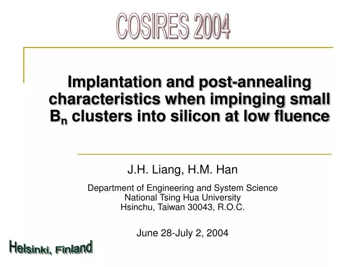
COSIRES 2004. Implantation and post-annealing characteristics when impinging small B n clusters into silicon at low fluence. J.H. Liang, H.M. Han Department of Engineering and System Science National Tsing Hua University Hsinchu, Taiwan 30043, R.O.C. June 28-July 2, 2004. Helsinki, Finland.

E N D
COSIRES 2004 Implantation and post-annealing characteristics when impinging small Bn clusters into silicon at low fluence J.H. Liang, H.M. Han Department of Engineering and System Science National Tsing Hua University Hsinchu, Taiwan 30043, R.O.C. June 28-July 2, 2004 Helsinki, Finland
Introduction • As the scale of modern devices becomes increasingly smaller, the formation of high-quality shallow junctions using the advanced Bn cluster ion implantation technique becomes more urgent. • In this study, an in-depth investigation of Bn cluster size and post-annealing dependence on the corresponding junction depth (xj) and sheet resistance (Rs) are extensively discussed.
Experimental Details • Specimen preparation: Specimens of 2 cm x 2 cm squares were well prepared from CZ-grown <100> n-type silicon wafers with a resistivity of 4-7 W-cm. • Ion implantation: Bn- (n=1-4) cluster ions were extracted from a source of negative ions by cesium sputtering (SNICS) on a NEC 9SDH-2 3MV tandem accelerator. Specimens with a tilt of 7o were room-temperature implanted with the Bn-cluster ions using the same atomic energy level (20 keV/atom) and atomic fluence (5×10¹³ atoms/cm2 ). The implanted area on the specimen was 1.5 cm in diameter.
Post-annealing treatments: one-step: RTA two-step: FA+RTA RTA = rapid thermal annealing at 1050 oC 10 s (Heatpulse 610i system) FA = furnace annealing at 550 oC 1 h (Lindber system) • Characteristic measurements: SIMS (IMS4F): boron depth profiles => xj (where CB = 1018 atoms/cm3) oxygen depth profiles four-point probe (Napson RT-7): sheet resistance => Rs
Results and discussion The mass spectrum of negative ions detected at the Faraday cup located behind the 30o inflection magnet with a slit size of 2 mm. • Bn- cluster ions can be successfully extracted. • B3- signal does not clearly discriminate from the O2- signal. • BO2- signal does not clearly discriminate from the B4- signal.
Average range (Rp), longitudinal range straggling (△Rp), skewness (g), and kurtosis (b) are 75 nm, 28 nm, -0.26, and 2.6 for boron atoms; 53 nm, 28 nm, 0.23, and 2.3 for recoiled silicon atoms. • Total defects peak at 54 nm. • The average ranges of the vacancy-rich, neutral, and interstitial-rich regions in the depth profile of net defects are 6, 23, and 84 nm. SRIM-calculated depth profiles of boron atoms, net defects, recoiled silicon atoms, and total defects for the as-implanted 20 keV B1 specimen. The implantation ion fluence is 5×10¹³ atoms/cm2 .
SIMS-measured depth profiles of oxygen atoms in the as-implanted B3 and B4 specimens. The implantation ion fluence is 5×10¹³ atoms/cm2 . • No indication of O2- contamination in the B3 implant. • BO2- ions do co-implant with B4- ions in the B4 implant.
SIMS-measured depth profiles of boron atoms in Bn specimens. The implantation ion fluence is 5×10¹³ atoms/cm2 . symbol:SIMS data ◇: as-implanted X: RTA annealed ◆: FA+RTA annealed line: Pearson distribution dashed: as-implanted dotted: RTA annealed solid: FA+RTA annealed
Measured range parameters, retained boron fluence, junction depth, and sheet resistance in the as-implanted and as-annealed Bn specimens.
as-implanted boron depth profile: • The clear-the-way and acceleration effects outweigh the nonlinear damage effect and cause the boron depth profile becomes broader and extends deeper into the specimen bulk as cluster size increases. That is, Rp , △Rp , g , and b increase as cluster size increases. • The increase in Rp , △Rp , g , and b inclines to reach a saturation point in larger cluster ions. • The variation of b versus g for all the implants of concern closely correlates to the parabolic fitting formula of b = 2.8 +2.4g 2 suggested by Gibbons.
RTA annealed boron depth profile: • In the B1 and B2 implants, the boron depth profile in the RTA annealed B2 specimen becomes significantly broader and extends much deeper into the specimen bulk than does that of the B1 implant. Rp , △Rp , g , and b increase as cluster size increases when compared to those of the as-implanted specimens. TED is stronger in the RTA annealed B1 and B2 specimens, thus leading to larger junction depths but smaller sheet resistance. • In the B3 and B4 implants, the boron depth profile in the RTA annealed B4 specimen becomes slightly broader but shifts a little more toward the specimen surface than does that the B3 implant. Rp decreases but △Rp , g , and b increase as cluster size increases when compared to those of the as-implanted specimens. . TED is smaller in the RTA annealed B3 and B4 specimens, thus results in smaller junction depths but larger sheet resistance. Oxygen contamination and greater residual defects in the near-surface region causes an anomalous increase in sheet resistance in the RTA annealed B4 specimen.
FA+RTA annealed boron depth profile: • In the B1 and B2 implants, Rp , △Rp , g , and b increase only slightly as cluster size increases when compared to those of the as-implanted specimens. • In the B3 and B4 implants, Rp and △Rp are practically unchanged while g and b increase slightly as cluster size increases when compared to those of the as-implanted specimens. • FA+RTA annealed boron depth profiles indeed show less TED when compared to those of RTA. • Less TED is obtained among the boron depth profiles in the FA+RTA annealed B1, B2, and B3 specimens and all the boron depth profiles are similar to each other. Therefore, the corresponding junction depth and sheet resistance varies insensitively to cluster size. • Oxygen contamination and greater residual defects in the near-surface region causes an anomalous increase in sheet resistance in the FA+RTA annealed B4 specimen.
Conclusions • The characteristics of the shallow junction produced by low-fluence small Bn cluster ion implantation are strongly dependent on cluster size as well as post-annealing method. • TED of boron atoms favors one-step RTA for smaller Bn cluster ions, but a noticeable reduction of TED is obtained for larger Bn cluster ions. • The TED of two-step FA+RTA is smaller than that of one-step RTA. • Sheet resistance of FA+RTA is larger than that of RTA in the B1 and B2 implants, indicating that boron activation favors RTA. • Sheet resistance of FA+RTA is smaller than that of RTA in the B3 and B4 implants, implying that crystalline recovery favors FA+RTA.
It is possible to use larger Bn cluster ions together with the subsequent FA+RTA method to obtain an optimum shallow junction without sacrificing extremely large sheet resistance. • The results of this study confirm the availability and feasibility of Bn cluster ion implantation as a novel technique in fabricating high-quality shallow junctions for modern devices.