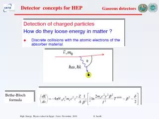
Bethe-Bloch formula
Bethe-Bloch formula. Cluster of electrons. Primary ionization. Total ionization. Cathode. The collection of these electrons on an appropriate electrode produces our signal. To drive the electrons towards the electrode an electric field is needed!. Anode. Drift and Diffusion.

Bethe-Bloch formula
E N D
Presentation Transcript
Bethe-Bloch formula
Cathode The collection of these electrons on an appropriate electrode produces our signal. To drive the electrons towards the electrode an electric field is needed! Anode Drift and Diffusion
Low electric field. Ionization region Number of electrons is independent on the applied field If the electric field is too low, there is recombination between ions
Ionization chambers A charge q at a distance xfrom the anode has U=qV(x) For a displacement of dxDU=qV(x+dx)-qV(x)=qEdx should be compensated from the power supply energy V0idt=V0dq qEdx=V0idt i=q(v/d) iis the current signal -Vo cathode x Constant electric filed E=V0/d d - q x anode signal R i
+ - + d - - + i(t) -HV R1 C1 t C2 A R2 If more clusters at different x, add all the contributions Q(t)=Si q0 If R2C2 e R2C1 small in comparison to t= d/v Current signal onR2 Q is the charge induced on the electrode We neglect the signal due to positive ions because they arrive much later
Cathode 1 cm of Argon produces about 100 electrons. Very small signal to detect. Amplification is needed!!! Anode Increase the electric field so that each primary electron is accelerated and gets enough energy to produce other ionizations d Average free path E = Townsend coefficient
Limited proportional M < 108 • Streamer 108 < M <1010 • Geiger M >1010
Gain Korff relation
C = capacitance / unit length Proportional region Collected charge proportional to initial ionization The cylindrical geometry is suitable to easily achieve high electric fields a = 8 10-5 m b= 10-2 m HV =500 V E = 5 104 V/m
Avalanche It develops close to central electrode at a radius of 4 10-4 m
anode 2a b R +V0 cathode Wire proportional chamber a= 10 mm, b=10 mm r’=a +1 mm The induced signal is due to positive ions
Cylindrical geometry is not the only one able to generate strong electric field
Noble gases emits photons if excited (argon emits 11.6 eV photons). Threshold energy for metal ionization is lower (e.g. Cu 7.7 eV) Quenchers The addition of polyatomic gases ( CH4,C4H10, ethane, CO2, BF3) is needed to absorb photons Already important in the proportional regime.
field lines and equipotentials around anode wires In 1968 Charpak proposed the first Multi Wire Proportional Chamber (MWPC) In an array of anodic tightly spaced wires, each is like a proportional counter. The position of the particle can be defined Typical parameters: L = 5 mm, d = 1÷2 mm, Rwire~ 20 mm
y L x d Anode Cathode (V=0) Cathode (V=0) Far from the anode the field is uniform. Each wire work as a ”proportional chamber” C is the capacity per unit length a = wire radius
L s However for inclined tracks , more wires may be involved • Different signal are generated but in different times. Our interest is for the first. • Therefore we can: • Set the gate of reading electronic system to accept only the fast signals; • Introduce a percentage of electronegative gas to stop the electrons generated far from anode.
Two coordinates Charge division Double layer of wires Time difference
The cathode strip chambers The cathode is segmented in strips where a signal is induced. If each strip is at the coordinate zi , the center o gravity is:
The avalanche around an anode wire creates an induced charge distribution on the cathode, with a FWHM roughly 1.5 times the anode to cathode distance. The CMS design
The CMS CSC s ~ 70 mm
x Measure arrival time of electrons at sense wire relative to a time t0. Drift Chamber
(U. Becker, in: Instrumentation in High Energy Physics, World Scientific) Advantage of drift chamber with respect to MWPC Easier mechanical construction (higher distance between wires) Lower number of wire less complex electronic (but more expansive) Higher precision (no more limited by the wire distance) Fundamental parameters Optimize geometry to have E constant Gas which allow constant drift velocity Vd (Vd ~ 50 mm/ms in Argon-Isobutene 75%-25% and E~700-800V/cm) Introduce field wires
field sense • Resolution determined by • diffusion, • path fluctuations, • electronics • primary ionization • statistics Resolution is better for tracks passing at larger distance from the sense wire… but at very large distance the diffusion enter in the game m m
Transverse diffusion substantially reduced in some gases if E || B
Cathode pads B Anode wires gas Central electrode (≈ -50kV) Read out plane TPC (Time Projection Chamber) Z coordinates measured by the drift time X and Y measured on anode wires and cathode pads Small quantity of material (only gas). Multiple-scattering and photon conversion is minimized z x y MWPC
gas volume with E & B fields B y drift E x z charged track wire chamber to detect projected tracks
The TPC allows to determine a point in the space ( x,y,z) The analog signal on the anode measures dE/dx E//B drift velocity parallel to E e B. Diffusion perpendicular to E is reduced. Electron move around B with a radius of about 1 mm (E ~ 50KV e B ~1.5 T ) Requirements: To measure Z is necessary a good knowledge of Vd Laser Calibration and correction for pressure and temperature needed Very clean gas Aleph TPC L = 4.4 m, Diameter = 3.6 m,
MWPC limitation Wire spacing: 1-2 mm Rate capability: limited by space charge
70 µm Gas Electron Multiplier (GEM) Thin metal-coated polymer foil chemically pierced by a high density of holes. On application of a voltage gradient, electrons released on the top side drift into the hole, multiply in avalanche and transfer the other side. Proportional gains above 103 are obtained in most common gases.
-VD 3 mm DRIFT -VTOP DVGEM MULTIPLICATION -VBOT 1 mm INDUCTION PATTERNED READOUT BOARD Basic GEM Detector • Readout separated from multiplying electrodes • Multiple cascaded structures possible (large gains, feedback suppression) • - Cheap and reliable
Ar-CO2 70-30 I+ e- Induction gap e- S1 S2 S3 S4 FAST ELECTRON SIGNAL No positive ion tail: very good multi-track and time resolution
Double GEM + readout pads Same gain at lower voltage Less discharges
EFFICIENCY FOR MINIMUM IONIZING PARTICLES 3 mm gap SPACE RESOLUTION ~ 40 µm rms CLUSTER SIZE ~ 500 µm FWHM A. Bressan et al, Nucl. Instr. And Meth. A425(1999)262
Saturated avalanche • Increase the gain up to 107 • Better signal • No need for amplification • But • Only position measurement • dE/dx no possible A small quantity of electronegative gas (freon ) is needed to reduce the number of electrons in the avalanche
Streamer mode - Geiger mode Gain > to 108 streamer spark Avalanche
Streamer • When the gain is greater then 10 8 (Raether limit) • The electron spatial charge produce a decrease of the electric field • Recombination e- -positive ions • Production of ultraviolet photons • Production of secondary avalanches from these photons E~0 , e-~108
The Geiger counter detects some or all of the four major types of ionizing radiation, namely Alpha, Beta, Gamma, and X-rays. Geiger –Muller counter in the Fermi laboratory A modern device A Geiger-Mueller (GM) tube is a gas-filled radiation detector. It commonly takes the form of a cylindrical outer shell (cathode) and the sealed gas-filled space with a thin central wire of about 30 mm (the anode) held at ~ 1 KV positive voltage with respect to the cathode. The fill gas is generally argon at a pressure of less than 0.l atm plus a small quantity of a quenching vapor.
Collisions with the fill gas produce excited states (~11.6eV) that decay with the emission of a UV photon and electron-ion pairs (~26.4 eV for argon). The new electrons, plus the original, are accelerated to produce a cascade of ionization called "gas multiplication" or a Townsend avalanche. The multiplication factor for one avalanche is typically 106 to 108.