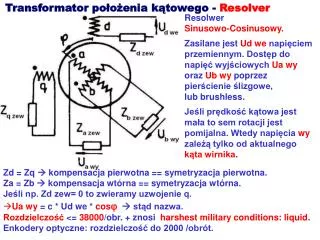
The Resolver
Sin (θ). Sin( ψ ). Switching Circuit. Sin( ψ ). Sin( ψ ). Cos( ψ ). Cos( ψ ). ε=Sin(θ-ψ). ε=Sin(θ-ψ). s in(θ) sin(ψ). Cos (θ) Cos(ψ). Sin(θ). Sin(θ). Cos(θ). Cos(θ). θ ψ. ψ. θ. Mp=20%. ts=25ms. DESIGN OF A PLL-BASED R/D CONVERTER FOR SERVOMOTOR CONTROL.

The Resolver
E N D
Presentation Transcript
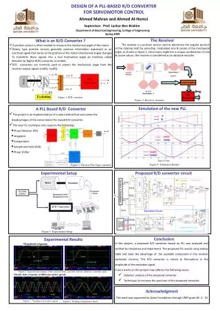
Sin(θ) Sin(ψ) Switching Circuit Sin(ψ) Sin(ψ) Cos(ψ) Cos(ψ) ε=Sin(θ-ψ) ε=Sin(θ-ψ) sin(θ)sin(ψ) Cos(θ)Cos(ψ) Sin(θ) Sin(θ) Cos(θ) Cos(θ) θψ ψ θ Mp=20% ts=25ms DESIGN OF A PLL-BASED R/D CONVERTER FOR SERVOMOTOR CONTROL Ahmed Mahran and Ahmed Al-Homsi Supervisor: Prof. Lazhar Ben-Brahim Department of Electrical Engineering, College of Engineering Spring 2009 • What is an R/D Converter ? • A position sensor is often needed to measure the mechanical angle of the motor. • Rotary type position sensors generally produce information expressed as an electrical signal that varies as the position of the motor (mechanical angle) changes. To transform these signals into a real mechanical angle an interface called Resolver-to-Digital (R/D) converter is needed. • R/D converters are normally used to extract the mechanical angle from the resolver output signals (sin(θ), cos(θ)). • The Resolver • The resolver is a position sensor used to determine the angular position of the rotating shaft by providing modulated sine & cosine of the mechanical angle, as shown in figure 2. Since every angle has a unique combination of sine & cosine values, the resolver is considered as an absolute encoder. Demodulator θ≈ψ R/D Converter Figure 1: R/D converter Figure 2: Resolver structure • A PLL Based R/D Converter • The project is an implementation of a new method that overcomes the disadvantages of the conventional PLL-based R/D converter. • The new PLL technique only requires the followings: • Simulation of the new PLL Radian • Phase Detector (PD) • integrator • Comparators • Sample and Hold (S/H) • Phase Shifter Time(x250us) Figure 4: Simulation Results Figure 3: The new PLL Type converter • Experimental Setup • Proposed R/D converter circuit θ≈ψ Figure 5: Experimental Setup • Figure 6: Transient performance of the proposed PLL converter with two different controller gains • Steady state response at different motor speeds Conclusion • In this project, a proposed R/D converter based on PLL was analyzed and verified by simulation and experiment. The proposed PLL avoids using lookup table and takes the advantage of the available component in the resolver excitation circuitry. This R/D converter is robust to fluctuations in the amplitude of the excitation signal. • Future works on this project may address the following issues: • Detailed analysis of the proposed converter . • Techniques to increase the precision of the proposed converter. • Experimental Results • Transient response Acknowledgment This work was supported by Qatar Foundation through UREP grant #4- 4 - 24 Figure 7 : Tracking at low motor speed Figure 8: Tracking at high motor speed