Download

1 / 58
580 likes | 762 Vues
Design and Fabrication 1212. Unit 1- Introduction to Design (10 hrs). Unit 1: Introduction. Topic 1-1: History of Design (1 hour) Topic 1-2: The Design Process (4 hours) Topic 1-3: Social/Environmental Considerations (2 hours) Topic 1-4: Design in Fabrication (2 hours)

E N D
Design and Fabrication 1212 Unit 1- Introduction to Design (10 hrs)
Unit 1: Introduction • Topic 1-1: History of Design (1 hour) • Topic 1-2: The Design Process (4 hours) • Topic 1-3: Social/Environmental Considerations (2 hours) • Topic 1-4: Design in Fabrication (2 hours) • Topic 1-5: Careers in Design (1 hour) This unit introduces students to the engineering design process and provides the basis for the remaining units. Students will review the history of the design process and examine how it has evolved. You will also examine various fabrication techniques and discover how design and fabrication are interrelated.
Unit 1- Introduction to Design (10 hrs) Topic 1 – History of Design
Topic 1 – History of Design The history of engineering can be roughly divided into four overlapping phases, each marked by a revolution: 1. Pre-scientific revolution: The prehistory of modern engineering features ancient master builders such as Leonardo da Vinci. 2. Industrial revolution: From the 18th through early 19th century, civil and mechanical engineers changed from artists to scientific professionals. 3. Second industrial revolution: In the century before WW II, science-based engineering branches developed electricity, telecommunications, cars, airplanes, and mass production. 4. Information revolution: As engineering science matured after the war, microelectronics, computers, and telecommunications jointly produced information technology. *See Handout LRS-U1-T1-1: Chronology of Design
Around the year 1400, he won a prestigious opportunity to design and build the dome of the "new" cathedral for the city of Florence. Brunelleschi was worried, however, that his contemporaries would try to steal his ideas, so to keep it secret he did something new. Brunelleschi kept a journal in which he sketched and described individual ideas. He distributed them to the various manufacturers. He then evaluated the concepts, blending some together and discarding others altogether. Finally he completed the dome. Brunelleschi had unwittingly invented a design process. The Design Process has evolved from an informal approach to a formal approach to one with defined steps and procedures. Italian architect, Filippo Brunelleschi (1377-1446), is attributed with creating the first formal approach to the Design Process! *See Handout: An Extremely Abbreviated History of Engineering Design
The design process has expanded into a multidisciplineapproach that relies on people with varied disciplines and backgrounds. Think about the following product: • How many people does it take to develop it? • Who are the various stakeholders? • Consider the disciplines of engineering, manufacturing, purchasing, marketing, and sales.
Greatest Designs of the 20th Century Explore the National Academy of Engineering’s list of the top 20 achievements How many of the 20th century's greatest engineering achievements will you use today? Why have these designs stood the test of time? Which of today’s designs do you think will remain significant in the future?
There are many historically noteworthy inventions and designs throughout history. Watch the following two videos and consider the impact of design and Inventions on the civilization Video 1: Roman Inventions Video 2: Inventions and Industry Can you determine some other significant designs and Inventions throughout history?
Unit 1- Introduction to Design (10 hrs) Topic 2 – The Design Process
The Design Process, is a methodology that can facilitate technological problem-solving. It is an iterative process that begins with an identified need or opportunity and progresses through a series of pre-defined steps to a final implemented solution. *See Handout LRS-U1-T2-1: The Design Process
Before you begin Opportunities (Need Identification) • Engineering design activity always occurs in response to a human need. Before you can develop a problem definition statement for a design problem, you need to recognize the need for a new product, system, or machine.
Step 1 - The Design Brief A critical step in design is to define the problem by identifying the design objectives or goals. For each objective, criteria that quantify or qualify the design objective must be assigned. • A Table may be used for organization
Step 2 - Investigative Research • Before you can go further in the design process, you need to collect all the information available that relates to the problem. Consider the following: • Suitable materials for your project. • Safety factors related to your design problem. • Write letters to manufacturers / shops. • Research using the library, Internet / CD-ROMs/DVDs. • Carry out a survey /questionnaire and present the results as a pictogram/table of results. • Collect pictures of existing products - photographs/catalogue pictures.
Step 3 - Generate Options • The next step in the design process begins with creativity in generating new ideas that may solve the problem. Start with existing solutions and then tear them apart-find out what's wrong with those solutions and focus on how to improve their weaknesses. • Draw at least 3 different ideas, with notes.
Once you've conceived alternative solutions to your design problem, you need to analyze those solutions and then decide which solution is best suited for implementation. Use a table, “Decision Matrix”, to indicate whether or not each of your alternative solutions meets the solution objectives by writing (Y)es or (N)o in the space provided. Step 4 - Select Best Option
Step 5 – Develop the Solution • The best solution option is developed in detail at this stage. This often involves various engineering calculations and the development of detail and assembly drawings. Following this, a physical or virtual prototype is usually produced and tested to ensure functional compliance.
Step 6 - Evaluation Redesign Evaluate your product. State the good and bad points. Does the solution answer the design brief ? Prototype testing will often reveal the need for improvement in a number of areas. The need to minimize weight and reduce production costs, for example, are sometimes identified at this stage. The design process essentially repeats at this stage in an effort to optimize the design – hence, design becomes a cyclic process.
Activities • Video: Wright Brothers -The Design Process (6 Segments) Class discussion • Handout LRS-U1-T2-2: Powered Wheel-Chair Design Assignment/Presentation • Handout ASG-U1-T2-1: Computer Workstation Design Assignment • Handout ASG-U1-T2-1-rubric • The class is divided into groups of 3. Each group should assign a recorder and presenter. Students then work in their individual groups to complete the assignment. At the end of the group work session, each student group presents their results.
Unit 1- Introduction to Design (10 hrs) Topic 3 – Social/Environmental Considerations
The production of common consumer products can have a considerable impact on society (health and the environment). These impacts can begin from the moment the raw materials are harvested, then processed into a finished product and to the point when the product is eventually disposed. Some questions to consider: Where do the materials to produce a common product such as a Tim Hortons coffee cup, used tire or cell phone, come from? What happens to the products after it is worn out? How could an improved design reduce negative environmental impacts.
Example: Discarding a Computer System The computer you're using to read this will one day be nothing more than a pile of garbage, contaminated with heavy metals and toxic plastic. There's lead in the keyboard, toxic flame retardants and antimony in the circuit boards, cadmium in the battery and the chips, all wrapped up in a casing of plastic that will release more deadly substances – furans and dioxins – when it's burned. Environment Canada estimates that computer waste in Canada – totalling more than 67,000 tonnes in 2005 – put 1.1 tonnes of mercury, 4.5 tonnes of cadmium and 3,012 tonnes of lead into landfills.
The Alternatives An improved design could minimize the negative impacts: • The newer flat screen monitor designs, for example, consist of fewer smaller components. • Batteries can be redesigned to last longer. Can you thing of some more options? What else can be done to reduce waste?
Assignment ASG-U1-T2-1Product Life Cycle and Environmental Impacts In groups of 2…Select a common consumer product such as a beverage container, an automobile tire, or a cardboard box and develop a 11” x 17” poster depicting the life cycle for that product. Your poster should include graphical illustrations and supporting text labels that help describe the life cycle from raw material to usable product to wasted, re-used or recycled product. Your poster should also include suggestions on how the product could be re-designed to minimize any negative environmental impacts.
APEGN APEGN (Association of Professional Engineers and Geoscientists of Newfoundland) members work as part of a team. An APEGN member should strive to influence the work in an environmentally responsible direction. Environmental degradation is recognized as a risk to public welfare, The long-term objectives are to sustain the viability of our ecosystems, and to ensure that the well being of future generations is not compromised by our activities today. To ensure this the association follows an Environmental Guideline when completing all projects. Handout: APEGN Environmental Guideline
Case Study On January 28, 1986, seven astronauts were killed when the space shuttle they were piloting, the Challenger the Challenger, exploded just over a minute into the flight. The failure of the solid rocket booster O-rings to seat properly allowed hot combustion gases to leak from the side of the booster and burn through the external fuel tank. The failure of the O-ring was attributed to several factors, including faulty design of the solid rocket boosters, insufficient low- temperature testing of the O-ring material and the joints that the O-ring sealed, and lack of proper communication between different levels of NASA management. Handout: ENGINEERING ETHICS The Space Shuttle Challenger Disaster Video: Challenger Disaster Also see: http://www.history.com/media.do?action=clip&id=mm_ed_challenger_broadband
Unit 1- Introduction to Design (10 hrs) Topic 4 – Design for Fabrication
Design for Manufacturing and Assembly Design impacts the manufacturing methods required and the associated differences in production cost. • It reduces part count thereby reducing cost. If a design is easier to produce and assemble, it can be done in less time, so it is less expensive. • It increases reliability, because if the production process is simplified, then there is less opportunity for errors. The following presentation adapted from Berkeley University Introduces some principles of design for manufacturing and assembly (DFM/DFA). These are summarized in the handout provided. Handout LRS-U1-T4-1 :Principles of Design for Manufacturing and Assembly
Minimize part count by incorporating multiple functions into single parts.
Before we look at some designs in further detail it is important to review the different Types of Drawings
1. WORKING DRAWING • A working drawing is the final ‘constructed’ drawing, produced as part of the design process. It usually consists of a front, side and top view of the solution. Dimensions are added so that any person using the working drawing can manufacture the design. Usually there are at least six dimensions but you can add as many as you feel are required in order for the manufacturer to make your solution. • The working drawing should be precise and drawn to a scale. If the drawing is half the size of the solution then the scale is 1:2. If the drawing is a 3rd the size of the solution then the scale is 1:3.
Sample Working Drawing ( 2 parts) - The drawing:
- the PARTS LIST • A ‘Parts List’ is a very important feature of the working drawing as all the parts are listed, with measurements. The materials used are also mentioned as well as the finish applied to the individual pieces. • Can you complete the parts list below? The working drawing clearly shows a clock with an electronic mechanism. Also included are hands and numbers.
A completed Working Drawing • The example shown below is of a pine box with a perspex lid. The box contains an educational toy.. The working drawing (seen below) is accurate and detailed so that a suitably skilled person could manufacture the design from the information shown.
2. Assembly drawings An assembly drawing shows the various parts of a product drawn to show exactly how they fit together. They are often used for products such as construction and model kits or flat-pack furniture, to show the user how to assemble the parts. They can be drawn in two ways. • A fitted assembly drawing shows the parts put together, and can be drawn in 2D or 3D. • An exploded drawing shows the parts separated, but in the correct relationship for fitting together. Exploded views are usually drawn in 3D, as illustrated. Image shows an assembly drawing, showing where screws are inserted to make joint.
Exploded views are often a good way of showing detail. The picture below shows the pens disassembled. It is important to recognize that all the parts are in line with each other, drawn usually along a centre line which is drawn through the entire centre of the design.
This is an example of a joint for wood called a comb or finger joint. In an exploded drawing the joint would be drawn disassembled (taken apart). In this way it is possible to see how the joints looks before it is glued together. An exploded view can make designs and ideas easier to explain especially when adding detailed notes.
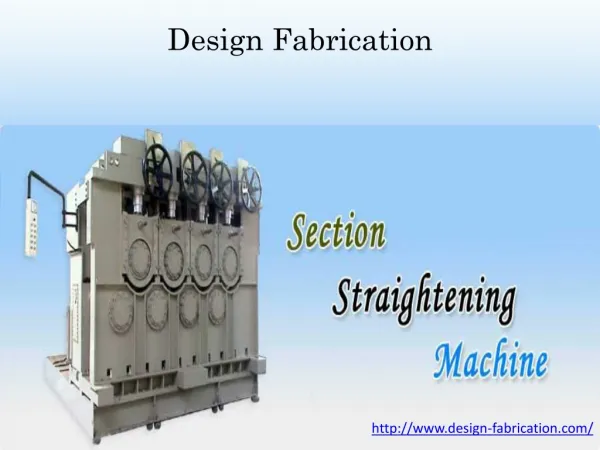
Other Types of Drawings 1. Section Drawings Section drawings usually show a cutaway view of an object.