Download
1 / 5
50 likes | 152 Vues
Explore the binary number system with a car odometer as we convert binary to decimal and learn about switches and LEDs in digital systems. Discover how to convert binary to decimal and vice versa using a binary positional weight chart. Experiment with switches and LEDs to understand binary input and output data in digital systems.

E N D
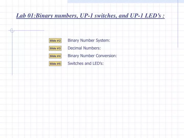
Lab 01:Binary numbers, UP-1 switches, and UP-1 LED’s : Binary Number System: Slide #2 Decimal Numbers: Slide #3 Binary Number Conversion: Slide #4 Switches and LED’s: Slide #5
Driver Viewing Window 9 9 9 0 0 0 1 0 1 1 1 0 0 0 0 1 0 0 0 0 1 0 Lab 01 : Binary Number System: We will use a car odometer to learn about the binary number system. A car odometer (non-digital) consists of a series of plastic discs that rotate to track the distance traveled by a car. A decimal odometer has the outer edge of each disc numbered from 0 … 9. Three discs will allow the odometer to record a maximum distance traveled of 999 Km’s. A binary odometer has the outer edge of each disc numbered with only 0 and 1. Using 3 discs will allow the odometer to record a maximum distance traveled of 111 binary Km’s … or … 7 km’s. Proceed to watch the odometer in action. 1 1 1 1 3 Bit Binary From the odometer example, you can place the 3 bit numbers in a table and see the order of the first 8 binary numbers. Slide #2
Hundreds Thousands Tens One’s 10-2 100 101 102 103 10-1 5 one’s 3 tens 2 Hundreds Lab 01 : Decimal Numbers : Reviewing some fundamental facts about the decimal number system will help you learn the binary number system. The decimal positional weight chart (PWC). Each numeral of a decimal number occupies a position that has a weight. Here is the decimal PWC. 2 3 5 The weight of each position have been given names. A decimal point is used to separate the whole part and the fractional part of a number. Here is the decimal number 235 placed in the PWC. Slide #3
4 20 21 22 23 1 2 2 8 32 16 8 4 1 1 1 0 1 Lab 01 : Binary Number Conversions : Digital systems process data in binary format. It is important to know how to convert back and forth from binary to decimal. Binary numbers are part of a base 2 number system. Only two numerals exist: 1 and 0. Converting binary to decimal: Drop the binary number into the binary PWC to convert it to decimal. Example convert 1101 to decimal. … Or … Binary PWC = 1x8 + 1x4 + 0x2 + 1x1 = 8+4+0+1 = 13 Converting decimal to binary: Example: convert 25 to binary Write down a binary PWC which the MSB (most significant bit) surpasses the number you are trying to convert. Work from MSB and use a 1 to include the bit position and a 0 to exclude it. The included bits should have their weight add up to the number being converted. Exclude because 16 + 8 + 2 will exceed 25. Include because 16 + 8 + 1 will equal 25. Include because 16 + 8 does not exceed 25. Exclude because 16 + 8 + 4 will exceed 25. Include because 16 does not exceed 25. Exclude because it would make number larger than 25 0 1 1 0 0 1 Slide #4
5v ON ON OFF OFF OFF ON 5v Logic 1 Logic 1 Logic 1 Input Output Logic 0 Logic 0 Logic 0 Digital System Lab 01 : Switches and LED’s: Students can create and test digital systems by using switches to represent binary input data and using LED’s (light emitting diode) to represent binary output data. Digital systems have an input side and an output side. Each arrow is a connection wire. The inputs of a digital system are binary digits (bits). You either input a binary 1 (logic 1) or a binary 0 (logic 0). The digital system processes the signals you have applied to the input and responds with binary 1 or binary 0 at the output(s). 5 volts represents a logic 1 and a 0 volts (also called GROUND or Gnd) represents a logic 0. The digital system is powered up by a 5 Volt power supply. A switch can be used to input a logic 1 and logic 0. An LED can be connected to the output to see the digital system’s response. Continue and you will see the switch and LED in action. Slide #5