Download
1 / 59
690 likes | 1.2k Vues
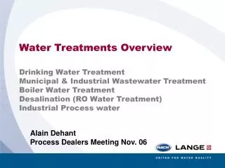
Water Treatments Overview Drinking Water Treatment Municipal & Industrial Wastewater Treatment Boiler Water Treatment Desalination (RO Water Treatment) Industrial Process water. Alain Dehant Process Dealers Meeting Nov. 06. Water Treatments Overview Drinking Water Treatment.

E N D
Water Treatments Overview Drinking Water Treatment Municipal & Industrial Wastewater Treatment Boiler Water Treatment Desalination (RO Water Treatment) Industrial Process water Alain Dehant Process Dealers Meeting Nov. 06
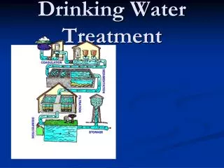
Water Treatments Overview Drinking Water Treatment Alain Dehant Process Dealers Meeting Nov. 06
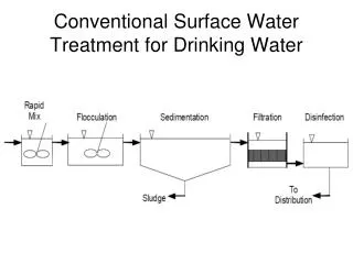
Turbidity pH Chlorine/Ozone Drinking Water Treatment Flow Diagram
Sludge Level Turbidity pH Chlorine Organics TOC/SAC Turbidity Sludge Conc. Turbidity Drinking Water Treatment Flow Diagram
pH Chlorine Chlorine Dioxyde Drinking Water Treatment Flow Diagram
Water Treatments Overview Municipal & Industrial Wastewater Treatment Alain Dehant Process Dealers Meeting Nov. 06
Municipal & Industrial Water Treatment Flow Diagram Municipal & Industrial Wastewater Treatment
Turbidity pH Municipal & Industrial Water Treatment Flow Diagram
Sludge Level Sludge Conc. Municipal & Industrial Water Treatment Flow Diagram
Dissolved Oxygen Turbidity/SS Organics (COD, BOD, TOC, SAC) Dissolved Oxygen Ammonia Nitrate Phosphorus Municipal & Industrial Water Treatment Flow Diagram
C -elimination Dissimilation (approx. 30 %) principle : C + O2 CO2 Assimilation (approx. 70 %) principle : C + O2 organic growth • So the main part of C-elimination is done via incorporating the carbon into undissolved bacteria mass and afterwards taking that bio-mass out of the water. • Only a minor part of the influents carbon is stripped as carbon-dioxid into the air. • Both is done by C -heterotroph bacteria under certain conditions like : • temperature between 5 - 33 °C pH-value between 6 - 8 • supply with degradable nutriments (C : N : P) • sufficient supply with dissolved oxygen (above 2,0 mg/l O2)
N –elimination (Nitrification) • WWTP´s influent contains nitrogen mainly as NH4 and organic N (like Urea, Proteins). • Due to the fact that NH4 at pH-levels above 8 is toxic to fish, Nitrification for N - elimination had been done since approx. 40 years : What is simplified mentioned under „principle“ is done by a very specific C -autotroph bacteria called nitrosomonas. Unfortunately the product of that micro-organismen work (NO2)is highly toxic to fish, so it is essential to operate a: Nitrification step I principle : NH4 + O2 NO2 that accrued NO3 is formed by another C -autotroph bacteria called nitrobacter. Unfortunately those don´t like the presence of NH4. So only if bothbacterias are acting synchroniously they can perform the complete 2-stage process of Nitrification in a sufficiant way. Nitrification step II principle : NO2 +O2 NO3
N –elimination (Denitrification) • The real decrease of total nitrogen in water is done by several specia of C -heterotroph micro-organismen. • They are called denitrificants and reducing the dissolved NO3 into molecular nitrogen (N2-gas), which can be stripped out of the water : Denitrification principle : NO3 N2 therefor the mentioned below conditions should be given : supply with degradable C-source (because bacteria is C -heterotroph) pH-value between 6,0 - 8,0 absence of dissolved oxygen (anoxic conditions) Denitrification as an advanced N -elimination is done in Germany since approx. 30 years.
P -elimination • This elimination can be done • by precipitants (chemical removal) • by bacteria (biological removal). Chemical removal principle : PO43- + Me3+ MePO4 By adding dissolved salts of aluminia or iron (Me3+) you can transfer the also dissolved ortho-phosphates into poorly soluable aluminia- or iron-phosphates, which can be taken out at the settling tank. necessary conditions: pH-value of 5,5 (FePO4) or 6,0 to 7,0 (AlPO4), which normally can´t be achieved on a WWTP an excess of aluminia- or iron-ions in ratio to the phosphates that have to be precipitated (so called „beta-value“)
P -elimination Biological removal principle: incorporation of dissolved phosphates based on a bacterias luxury-uptake-effect (to TAKE up more phosphates, than bacteria formerly had GIVEN up) necessary conditions are : systematic change between anaerob (NO solved or bounded oxygen) conditions (PO43- is given up) and aerob conditions (PO43- is taken up) supply with degradable C-source during the anaerob stage
Sludge Level Turbidity/SS Organics (COD, BOD, TOC, SAC) Nitrate Ammonia Phosphorus Sludge Conc. Sludge Conc. Municipal & Industrial Water Treatment Flow Diagram
Chlorine Municipal & Industrial Water Treatment Flow Diagram
Suspended Solids (SS) Municipal & Industrial Water Treatment Flow Diagram
Water Treatments Overview Boiler Water Treatment Alain Dehant Process Dealers Meeting Nov. 06
Silica, Sodium, Hardness Alcalinity, pH, Conductivity Turbidity Boiler Water Treatment Flow Diagram
Silica, Hydrazine, Phosphare, pH Ammonia Alcalinity Silica, Phosphate, pH, Conductivity Silica, Phosphate, pH, Conductivity Alcalinity, Hardness, Hydrazine Turbidity Boiler Water Treatment Flow Diagram
Silica, Hardness Conductivity, Turbidity Dissolved Oxygen Boiler Water Treatment Flow Diagram
Water Treatments Overview Desalination (RO Water Treatment) Alain Dehant Process Dealers Meeting Nov. 06
WATER DESALINATION BY REVERSE OSMOSIS FLOW DIAGRAM MULTI-MEDIA FILTER ACID DOSING SCALE INHIBITOR DOSING CHLORINE DOSING REVERSE OSMOSIS WASTE SEA WATER PRODUCT HIGHPRESSUREPUMP 5 µm CARTRIDGE FILTER REJECT BRINE CAUSTIC SODA DOSING CHLORINE DOSING BACKWASH FINAL PRODUCT WATER TANK PURGE PRODUCT WATER TANK DISTRIBUTION
WATER DESALINATION BY REVERSE OSMOSIS FLOW DIAGRAM MULTI-MEDIA FILTER ACID DOSING SCALE INHIBITOR DOSING CHLORINE DOSING REVERSE OSMOSIS WASTE SEA WATER PRODUCT HIGHPRESSUREPUMP 5 µm CARTRIDGE FILTER REJECT BRINE CAUSTIC SODA DOSING CHLORINE DOSING BACKWASH FINAL PRODUCT WATER TANK PURGE PRODUCT WATER TANK DISTRIBUTION Pre-Treatment
WATER DESALINATION BY REVERSE OSMOSIS FLOW DIAGRAM MULTI-MEDIA FILTER ACID DOSING SCALE INHIBITOR DOSING CHLORINE DOSING REVERSE OSMOSIS WASTE SEA WATER PRODUCT HIGHPRESSUREPUMP 5 µm CARTRIDGE FILTER REJECT BRINE CAUSTIC SODA DOSING CHLORINE DOSING BACKWASH FINAL PRODUCT WATER TANK PURGE PRODUCT WATER TANK DISTRIBUTION RO
WATER DESALINATION BY REVERSE OSMOSIS FLOW DIAGRAM MULTI-MEDIA FILTER ACID DOSING SCALE INHIBITOR DOSING CHLORINE DOSING REVERSE OSMOSIS WASTE SEA WATER PRODUCT HIGHPRESSUREPUMP 5 µm CARTRIDGE FILTER REJECT BRINE CAUSTIC SODA DOSING CHLORINE DOSING BACKWASH FINAL PRODUCT WATER TANK PURGE PRODUCT WATER TANK DISTRIBUTION Post-Treatment
Suspended solids and other particles in the feed water must be removed to reduce fouling of the membrane. Suspended solids are removed with coagulation and filtration. MULTI-MEDIA FILTER ACID DOSING SCALE INHIBITOR DOSING CHLORINE DOSING REVERSE OSMOSIS WASTE SEA WATER PRODUCT HIGHPRESSUREPUMP 5 µm CARTRIDGE FILTER REJECT BRINE CAUSTIC SODA DOSING CHLORINE DOSING BACKWASH FINAL PRODUCT WATER TANK PURGE PRODUCT WATER TANK DISTRIBUTION
Polyelectrolyte and ferric sulfate are injected at this point for in-line coagulation MULTI-MEDIA FILTER ACID DOSING SCALE INHIBITOR DOSING CHLORINE DOSING REVERSE OSMOSIS WASTE SEA WATER PRODUCT HIGHPRESSUREPUMP 5 µm CARTRIDGE FILTER REJECT BRINE CAUSTIC SODA DOSING CHLORINE DOSING BACKWASH FINAL PRODUCT WATER TANK PURGE PRODUCT WATER TANK DISTRIBUTION
Multi-media filter consist of: gravel, coarse sand, fine garnet, fine sand and anthracite. MULTI-MEDIA FILTER ACID DOSING SCALE INHIBITOR DOSING CHLORINE DOSING REVERSE OSMOSIS WASTE SEA WATER PRODUCT HIGHPRESSUREPUMP 5 µm CARTRIDGE FILTER REJECT BRINE CAUSTIC SODA DOSING CHLORINE DOSING BACKWASH FINAL PRODUCT WATER TANK PURGE PRODUCT WATER TANK DISTRIBUTION
MULTI-MEDIA FILTER ACID DOSING SCALE INHIBITOR DOSING CHLORINE DOSING REVERSE OSMOSIS WASTE SEA WATER PRODUCT HIGHPRESSUREPUMP 5 µm CARTRIDGE FILTER REJECT BRINE CAUSTIC SODA DOSING CHLORINE DOSING BACKWASH FINAL PRODUCT WATER TANK PURGE Multi-media filter is monitored for pressure drop. Backwash of the filter is necessary to assure a SDI less than 3,0 PRODUCT WATER TANK DISTRIBUTION
MULTI-MEDIA FILTER ACID DOSING SCALE INHIBITOR DOSING CHLORINE DOSING REVERSE OSMOSIS WASTE SEA WATER PRODUCT HIGHPRESSUREPUMP 5 µm CARTRIDGE FILTER REJECT BRINE CAUSTIC SODA DOSING CHLORINE DOSING BACKWASH Dosage of acid (HCl or H2SO4) is used to remove bicarbonate ions followed by aeration to remove CO2. FINAL PRODUCT WATER TANK PURGE PRODUCT WATER TANK DISTRIBUTION
MULTI-MEDIA FILTER ACID DOSING SCALE INHIBITOR DOSING CHLORINE DOSING REVERSE OSMOSIS WASTE SEA WATER PRODUCT HIGHPRESSUREPUMP 5 µm CARTRIDGE FILTER REJECT BRINE CAUSTIC SODA DOSING CHLORINE DOSING BACKWASH Anti-scalant (Phosponate or polyphosphate) is added to prevent scaling inside the RO system. FINAL PRODUCT WATER TANK PURGE PRODUCT WATER TANK DISTRIBUTION
MULTI-MEDIA FILTER ACID DOSING SCALE INHIBITOR DOSING CHLORINE DOSING REVERSE OSMOSIS WASTE SEA WATER PRODUCT HIGHPRESSUREPUMP 5 µm CARTRIDGE FILTER REJECT BRINE CAUSTIC SODA DOSING CHLORINE DOSING BACKWASH These anti-scalants are efficients against precipitation of CaCO3, CaSO4, SrSO4 & BaSO4, but are less effective in the case of silica precipitation. FINAL PRODUCT WATER TANK PURGE PRODUCT WATER TANK DISTRIBUTION
After anti-scalant injection, the flow continues through a 5 µm cartridge filter. MULTI-MEDIA FILTER ACID DOSING SCALE INHIBITOR DOSING CHLORINE DOSING REVERSE OSMOSIS WASTE SEA WATER PRODUCT HIGHPRESSUREPUMP 5 µm CARTRIDGE FILTER REJECT BRINE CAUSTIC SODA DOSING CHLORINE DOSING BACKWASH FINAL PRODUCT WATER TANK PURGE PRODUCT WATER TANK DISTRIBUTION
MULTI-MEDIA FILTER ACID DOSING SCALE INHIBITOR DOSING CHLORINE DOSING REVERSE OSMOSIS WASTE SEA WATER PRODUCT HIGHPRESSUREPUMP 5 µm CARTRIDGE FILTER REJECT BRINE CAUSTIC SODA DOSING CHLORINE DOSING BACKWASH Algae and bacteria can grow, so biocide (usually less than 1 mg/l chlorine) is required to clean the system FINAL PRODUCT WATER TANK PURGE PRODUCT WATER TANK DISTRIBUTION
MULTI-MEDIA FILTER ACID DOSING SCALE INHIBITOR DOSING CHLORINE DOSING REVERSE OSMOSIS WASTE SEA WATER PRODUCT HIGHPRESSUREPUMP 5 µm CARTRIDGE FILTER REJECT BRINE CAUSTIC SODA DOSING CHLORINE DOSING BACKWASH Some RO membranes can not tolerate chlorine, so dechlorination techniques are required. FINAL PRODUCT WATER TANK PURGE PRODUCT WATER TANK DISTRIBUTION
MULTI-MEDIA FILTER ACID DOSING SCALE INHIBITOR DOSING CHLORINE DOSING REVERSE OSMOSIS WASTE SEA WATER PRODUCT HIGHPRESSUREPUMP 5 µm CARTRIDGE FILTER REJECT BRINE CAUSTIC SODA DOSING CHLORINE DOSING BACKWASH Ozone or UV light may also be used to remove marine organisms. If ozone is used, it must be removed with chemicals before reaching the membrane. FINAL PRODUCT WATER TANK PURGE PRODUCT WATER TANK DISTRIBUTION
Operating pressure vary between 10-25 bars for brackish water and 50 – 200 bars for seawater. MULTI-MEDIA FILTER ACID DOSING SCALE INHIBITOR DOSING CHLORINE DOSING REVERSE OSMOSIS WASTE SEA WATER PRODUCT HIGHPRESSUREPUMP 5 µm CARTRIDGE FILTER REJECT BRINE CAUSTIC SODA DOSING CHLORINE DOSING BACKWASH FINAL PRODUCT WATER TANK PURGE PRODUCT WATER TANK DISTRIBUTION
Water quality depends on membrane rejection properties. MULTI-MEDIA FILTER ACID DOSING SCALE INHIBITOR DOSING CHLORINE DOSING REVERSE OSMOSIS WASTE SEA WATER PRODUCT HIGHPRESSUREPUMP 5 µm CARTRIDGE FILTER REJECT BRINE CAUSTIC SODA DOSING CHLORINE DOSING BACKWASH FINAL PRODUCT WATER TANK PURGE PRODUCT WATER TANK DISTRIBUTION