Linking
Linking. A quick overview of how to configure PulseWorx UPB devices to control each other. Powerline Control. The Old Way. Transmitting Device. A1 On. ID = A1. Receiving Device. Powerline Control - The Old Way. We are used to powerline devices having a single id ( e.g. A1 ).

Linking
E N D
Presentation Transcript
Linking A quick overview of how to configure PulseWorx UPB devices to control each other
Powerline Control The Old Way
Transmitting Device A1 On ID = A1 Receiving Device Powerline Control - The Old Way • We are used to powerline devices having a single id (e.g. A1). • We controlled that device by sending it simple powerline commands: • A1 On • A1 Off • A1 Dim • Etc.
The Old Way – Problems • Problems arose when we wanted to control more than one device at a time (e.g. Scenes). • Either multiple commands had to be sent one after another (macros): • A1 On followed by: • A2 Dim followed by: • Etc… • Or else devices had to have more than one id that they responded to…
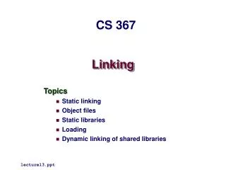
Problems The Old Way – cont. • Old Powerline Control methods provided a very small, inflexible set of commands: • On, Off, Bright, Dim, All On, All Off, Etc… • No commands were provided specifically to activate Scenes • Old Powerline Control methods provided limited device addressing methods: • 16 House Codes • 16 Device Codes
Powerline Control The New Way! UPB™
UPB ™ Powerline Control • When PCS invented the UPB ™ powerline communications protocol they allowed their PulseWorx devices to be assigned multiple ids that they respond to. • One ID is known as the device’s Unit ID. • The other IDs are known as the device’s Links. • There are 250 Links available per network. • Wall Switch Dimmers can be assigned as many as 16 Links. • Some other devices can be assigned as many as 32 Links.
What is a Link? • A Link is a special object with a unique identifier (number) that can be stored in the memory of a UPB™ device for the purpose of establishing a powerline communication relationship between devices. • Links are created in UPStart. • Links are stored in UPB devices’ non-volatile memory. • Links can be given meaningful names in UPStart. • Links are used for linking device components together.
UPB Network Transmit Component Powerline Message Powerline Message Receive Component Link 001 Device A Device B What Is Linking? • Linking is a UPB™ term to describe the process of establishing a powerline communication relationship (channel) between transmitting components and receiving components. • Powerline messages can be sent and received by devices on the same Link.
Link 001 Device B Device C Device D Link 001 Link 001 Link 001 What Is Linking? – cont. • Linking is easy! • It is accomplished by storing the same Link in both a Transmit Component and (one or more) Receive Components. • Powerline commands can be sent from one device on the Link to all other devices on the same Link. Device A Link 001 Commands
Transmit Components (Pushbuttons) E F G H I J Transmit Components (Rockers) K L What Is A Transmit Component? • A Transmit Component is a portion of a UPB device that triggers the transmission of a Command onto the powerline. • Pushbuttons • Rocker Switches • Input Switches • Doorbell Inputs • Telephone Inputs • Etc…
Receive Components (Presets) E F G H Receive Components (Indicators) I J K L What Is A Receive Component? • A Receive Component is a portion of a UPB device that accepts powerline Commands sent to its Link. • Presets • Output Channels • Indicators • Etc…
Device A Link 001 Goto 100% Link 001 E F G H I J Device B Device C Device D K L Link 001 Link 001 Link 001 What Is Linking? – cont. • Linking allows a single powerline command (e.g. Goto 100%) to affect multiple devices at once. • There is no limit to the number of components that can be Linked together. • Linking makes Scene creation easy.
Device A Link 001 Activate Link 001 E F G H I J 50% 100% 0% K L Link 001 Link 001 Link 001 Scene Control • A special UPB Command exists for activating a Link’s Receive Components to their preset levels and states. • The Activate command: • Causes receiving devices to go to their preset levels and states. • Some devices have preset Fade Rates too. • Scenes! Scenes! Scenes!
How To Link As Easy As 1-2-3
How To Link • Linking is done with the UPStart Setup Tool software. • Linking is as easy as 1-2-3: • Create the Link. • Assign the Link to a Transmit Component. • Assign the Link to a Receive Component.
Creating A Link • Many ways to create a Link. • One way to is to right-click in the Display pane and choose the Add Link… menu item. • Another way is to right-click on the Links tree of the Design Pane and select the Add Link… menu item.
Creating A Link – cont. • Another way to create a Link is to open the Link Viewer: • Network Link Names… • Then press the New button…
Creating A Link – cont. • UPStart allows you to give your Links IDs and meaningful names. • Automatically suggests next available Link ID. • UPStart v4.1 includes a Visual Link Editor: • Icon based • Drag-and-Drop
Assign Link To Tx Component • There are many ways to assign a Link to a Transmit Component: • One way is to edit a device and use its Transmit Components tab to assign the Link to the desired Transmit Component.
Add Controller Assign Link To Tx Component • Another way to assign a Link to a Transmit Component is to open the Link Builder interface for the specified Link. • Then assign a Transmit Component (Controller) to it using the Add Controller button.
Drag-and-Drop Assign Link To Tx Component • Another way to assign a Link to a Transmit Component is to open the Visual Link Editor available in UPStart v4.1. • The VLE allows you to drag-and-drop Transmit Components into a Link.
Assign Link To Rx Component • There are many ways to assign a Link to a Receive Component: • One way is to edit a device and use its Receive Components tab to assign the Link to the desired Receive Component.
Add Preset Assign Link To Rx Component • Another way to assign a Link to a Receive Component is to open the Link Builder interface for the specified Link. • Then assign a Receive Component (Preset) to it using the Add Preset button.
Drag-and-Drop Assign Link To Rx Component • Another way to assign a Link to a Receive Component is to open the Visual Link Editor available in UPStart v4.1. • The VLE allows you to drag-and-drop Receive Components into a Link.
Linking Multiple Devices • More than one device’s Receive Components can be Linked together. • This can be used to activate dramatic Scenes! • There is no limit to the number of components that can be Linked together…
Transmitting On Links The Next Step
Transmitting On Links • Now that you have Transmit Components Linked to Receive Components it is time to: • Configure how your Transmit Components will transmit on that Link. • Configure how your Receive Components will react to the Activate/Deactivate commands (optional).
Configuring Transmit Components • Depending on the type of device, configuring Transmit Components can be a little tricky. • In all cases, however, you will be answering two basic questions: • What Events will cause that component to transmit. • What Command(s) will be transmitted upon those events.
Transmit Component - Events • PulseWorx Pushbuttons recognize four events: • Single-Tap • Double-Tap • Hold • Release
Transmit Component - Events • PulseWorx Input sensors recognize two events: • Input Open • Input Close
Transmit Component - Commands • Each Event can be assigned at least one Command (from a list) that will be transmitted to the Link whenever that Event occurs. • Most Events allow you to choose two Commands: • Toggles between these two Commands each time the Event occurs. • If you don’t want toggling just assign both Commands to be the same thing.
Transmit Component - Commands • Goto Off – All devices on the Link go to 0% at their default fade rate. • Goto On – All devices on the Link go to 100% at their default fade rate. • Fade Down – All dimming devices on the Link fade to 0% at their default fade rate. • Fade Up – All dimming devices on the Link fade to 100% at their default fade rate. • Fade Stop - All dimming devices on the Link immediately stop fading.
Transmit Component - Commands • Deactivate - All devices on the Link go to 0% at their preset fade rate. • Activate - All devices on the Link go to their preset Level (or State) at their preset fade rate. • Snap Off - All devices on the Link go to 0% immediately (snap). • Snap On - All devices on the Link go to 100% immediately (snap).
Transmit Component - Commands • Quick Off – All devices on the Link go to 0% at the 0.8 second fade rate. • Quick On – All devices on the Link go to 100% at the 0.8 second fade rate. • Slow Off – All devices on the Link go to 0% at the 6.6 second fade rate. • Slow On – All devices on the Link go to 100% at the 6.6 second fade rate. • Blink - All devices on the Link blink off and on at a 0.5 second blink rate.
Transmit Component - Modes • With as many as two Commands being assigned to as many as four Events for as many as eight Pushbuttons it can become quite cumbersome to configure the Transmit Components on a single device (let alone 20 or more devices)…
Transmit Component - Modes • UPStart provides a simple shortcut method (called Button Modes) to help you specify some of the more common Transmit Component configurations. • Button Modes allows you to select a common configuration of Commands for each Event. • Each Button Mode specifies two Commands for each of the Events.
Transmit Component - Modes • EXAMPLE – The Super Toggler Button Mode: • Single-Tap – Toggles between activating and deactivating linked devices’ presets. • Double-Tap – Toggles between snapping linked devices on and off. • Hold – Toggles between fading linked devices up and down. • Release – Stops linked devices from fading.
Receiving On Links The Final Step
Receive Components - Presets • Receive Components are assigned to a Link and therefore will respond to whatever Commands are transmitted to that Link: • Goto 100% @ Fade Rate #0 • Goto 50% @ Fade Rate #5 • Goto 0% @ Default Fade Rate • Start Fade to 100% @ Fade Rate #3 • Stop Fade • Blink • Etc…
Activate/Deactivate • UPB™ has two special commands available (Activate and Deactivate) designed for Scene control. • Each Receive Component has an associated set of configuration arguments (called Presets) that get invoked by the Activate and Deactivatecommands. • A Wall Switch Dimmers contain 16 Receive Components/Presets. • Each Preset specifies a Light Level and a Fade Rate. • The Activate command activates the preset Light Level and Fade Rate. • The Deactivate command sets the Light Level to 0% at the preset Fade Rate.
Device A Link 001 Activate Link 001 E F G H I J 50% 100% 0% K L Link 001 Link 001 Link 001 Activating A Scene • The Activate command will activate each linked Receive Component’s Preset. • Each device can have a different Light Level and Fade Rate! • A single pushbutton press activates a Scene.
Presets • Each Receive Components’ Preset can be configured using UPStart. • Select the Light Level and Fade Rate to be invoked by the Activate and Deactivate commands.
Presets – cont. • Note: Preset light levels can be adjusted by the homeowner after installation using a keypad controller. • Set all of the dimmers on a Link to the desired Light Level. • Press the pushbutton that activates that Link 5 times in a row. • All Receive Components then store their current Light Levels.
Using The Scene Builder Interface Available in UPStart v4.0
Press Scene Edit The Scene Builder • UPStart v4.0 provides an even easier way to link components together and specify their transmit and receive properties. • The Scene Builder: • Open the Link Names Table • Select an existing Link or create a New one • Press the Scene Edit button. • This brings up the Scene Builder interface for the selected Link.
The Scene Builder • Add one or more unused Transmit Components (e.g. Pushbuttons) to the Controllers tab.
The Scene Builder • Add one or more unused Receive Components (e.g. Presets) to the Presets tab.
The Scene Builder • Assign a Button Mode to each Transmit Component. • Press the mode button to select whichever standard Button Mode you desire.
The Scene Builder • Assign a Light Level and Fade Rate to each Receive Component.