Straw electronics
Straw electronics. Straw Readout Board (SRB). Full SRB - IO. Handling 16 covers Input 16*2 links 400(320eff) Mbits /s Control TTC LEMO VME Output to PC farm – 2*1Gb/s ethernet VME to SBC L0 trigger Choke/error. Straw detector output data flow. Straw detector 4 chambers

Straw electronics
E N D
Presentation Transcript
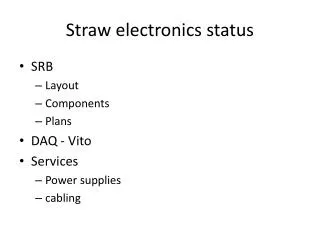
Straw electronics Straw Readout Board (SRB)
Full SRB - IO • Handling 16 covers • Input 16*2 links 400(320eff) Mbits/s • Control • TTC • LEMO • VME • Output • to PC farm – 2*1Gb/s ethernet • VME to SBC • L0 trigger • Choke/error
Straw detector output data flow • Straw detector • 4 chambers • 4 views each (x,y,u,v) • ½ view is served by SRB (Straw Readout Board) • 2 SRBs/view • 8 SRBs/chamber • 32 SRBs/detector • 2 x 1Gbit/s ethernet interfaces per SRB • 1 chamber connected through 10Gbit link (+1 spare) to pc-farm • 16 Gbit links merged in a switch
Data rates • Single straw rate 60kHz (average) • 48 bits/event (24 bits leading, 24 bits trailing) • Coarse time in header • L0 1MHz rate with time window 250ns • Total data rate per SRB with protocol (UDP,IP,..) • 440 Mbit/s • Total data rate per chamber with protocol • 3.6 Gbit/s • Full detector ~16Gbit/s • Without L0 and without protocol • 600->800 Mbit/s per SRB • Full data 4.8->6.4 Gbit/s per chamber
SRB – components L0 PROCESSOR L0 OUT ETH L0 LOOK_UP TABLE L0 OUT SRB VME INTF ON-LINE MONITOR LEMO TTC TTCRx COVERS TIME REMAP DATA TO PC FARM COVER CONTROL, DATA, SYNCH EVENT PROCESSOR 2(4)GB DDR3
SRB – control flow VME to - Setup - Control, - On-line monitoring - Data • Selectable control • TTC • LEMO • VME Clock delay to compensate time of flight, Group of 4 covers
SRB – data flow VME 2.5Gbit/s Alternative path 16x2x320Mbit/s ~10Gbit/s 2x Gbitethernet
SRB – trigger data flow L0 PRIMITIVES VME 2.5Gbit/s 16x2x320Mbit/s ~10Gbit/s Alternative path 2x Gbitethernet
Trigger • First mentioned in TD • Possibility to use Straw detector for L0 if proved to be useful • Tracks or hit multiplicity • Tracks • View is split to corridors • 6 straws • Corridors overlap on each side by 2 straws • 2 or more trailing edges in a corridor in a defined time window qualify a track • Can be already used as a coarse position ~13mm
Trigger • Position can be improved using leading edges • Leading edges from 6 straws put into the time pipeline corresponding to the full drift time in straw, step 25ns • Trailing edge track signal starts pattern recognition • Leading edges are run though look-up table and output position code • Time-corresponding position codes from all views are combined To look-up table 6 straws leading edges
Trigger • 1 SRB with modified firmware collects primitives from 8 SRBs serving 1 chamber • OR • 1 SRB with modified firmware collects primitives from 16 SRBs serving 2 chambers • Chambers 1,2 and 3,4 can either contribute alone or can be combined • L0 SRB send L0 primitives to L0 processor • Time estimate • Event to Cover to SRB – <500ns • Time-reordering of hits - 10us • Track finding - <1us • Collection of hits and combination < 10us • Sending L0 primitives in < 22us
Choke/error • Use user-defined VME P2 line • Open collector output from every SRB • Wire-OR to combine all outputs • Simple VME board to convert choke/error wire-OR signals to RJ45 standard • Use 1 calorimeter choke/error collection board to combine outputs from all chambers and send to L0 processor • Monitoring via VME
SRB conclusions • Design started • Schematics • Big part of prototype board firmware could be reused • New parts • Time reordering • Event buffer management • data format for pc-farm • Online monitoring • L0 trigger • Ready for PCB layout in November • Prototype January/February 2014 • Price estimate • Components < 1 kCHF • PCB + assembly < 1 kCHF • Total < 2 kCHF • Integration/dry-run between April-June 2014