Download
1 / 21
250 likes | 377 Vues
Explore the foundational elements of geometric construction and modeling, focusing on points, lines, polygons, curves, and solids. Learn essential techniques for accurately drawing straight and curved lines, creating polygons, and understanding the significance of angles. Discover how to utilize scales for precise measurements and delve into the concepts of extruded and revolved solids in CAD. With practical exercises and worksheets, this guide will enhance your ability to visualize and create 2D sketches and 3D models, essential skills for any aspiring designer or architect.

E N D
Points • A point represents a location in space or on a drawing. It has no width, height or depth. • Sketch points by a short crossbar on a line, or by a small cross.
Lines • A straight line is the shortest distance between two points. • Parallel lines • Intersecting lines • Perpendicular lines
Drawing Straight Lines • Always use some sort of straight edge (Triangle, ruler, credit card, etc.) • Line weights must be consistent. Rotating the pencil as you draw the line keeps the lead tip width consistent. • Lines need to begin and end crisply. • Line intersections must connect and not overshoot. • Good Lighting is essential to seeing where to draw lines when using mechanical tools.
Drawing Parallel & Perpendicular Lines • Parallel lines are drawn using a straight edge (can be a triangle) and a triangle. See Figure 12.19 (pg 146) of text. Straight edge must not move. • Perpendicular lines are drawn with same instruments.
Practice! • Draw 3 parallel lines 6” long and 1.5” apart, p146 • Construct a perpendicular bisector to the bottom line using a compass, p144 • Connect them at the ends and midpoint with a perpendicular line using a triangle • Draw a random angle 30 – 170 degrees and construct its bisector, p145 • Do Worksheet 7, parts 1, 2, 5, 6
Drawing Lines at Angles that are a Multiple of 15 degrees • Using a horizontal reference and the two basic triangles, any angle that is a multiple of 15 degrees can be drawn. • The angles are the sum or difference of 30, 45, or 60 degrees which can be obtained by the combination use of the two standard triangles. • A protractor may be used to assist in constructing lines at other angles.
Drawing Curved Lines • General curves are drawn by plotting points along a line then using an irregular curve (normally a French curve) or a Spline to connect the points.
Scales • Scales are used to measure distances. • Drawings are often not done at the same size, or “scale”, as the object being drawn. • There are many types of scales available. • The text (p123-128) has a good discussion (with illustrations) on how to read a scale.
Polygons • A polygon is any plane figure bounded by straight lines. A Pentagon
Regular Polygons • Regular polygons have equal angles and equal sides. • They are often created and described by inscribing them in a circle, or circumscribing them about a circle. • Hex head bolts are a typical example
Circles • A circle is a closed curve, all points of which are equally distant from the center. • Circumference equals pi times the diameter C =p d
Practice! • Do Worksheet 6 (see p143, 144) • Do Worksheet 8 (see p147-149) • Do Worksheet 9 (see p150-151) • Do Worksheet 10 (see p152)
Extruded Solid • CAD construction for a 3D part having a uniform cross section. • Named for the manufacturing process of forming material by forcing it through a shaped opening.
Revolved Solid • construction by revolving a uniform cross-section along a circular path.
Boolean Operators • Venn diagrams can be used to show Boolean operations. • Union (addition) • Difference (subtraction) • Intersection
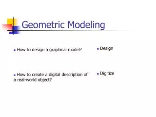
Summary • Points, lines, and circles are the basic geometric elements used to make 2D sketches. • Using CAD you can create 3D models. • Understanding geometric solids can help you create CAD models and interpret and visualize from 2D sketches and drawings.