Computer Aided Design
Computer Aided Design. Course 2. Setting up Analyses


Computer Aided Design
E N D
Presentation Transcript
Computer Aided Design Course 2
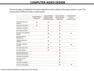
Setting up Analyses In order to measure a circuit performance, it is necessary to simulate its behavior. PSpice A/D is a simulation program that models the behavior of a circuit containing any mix of analog and digital devices. Used with Schematics for design entry, you can think of PSpice A/D as a software-based breadboard of your circuit that you can use to test and refine your design before ever touching a piece of hardware.
For the circuit to be simulated you need to setup the analyses first. Certain analyses (such as noise, Monte Carlo, sensitivity/worst-case, DC sensitivity, Fourier, and small-signal DC transfer function) require you to specify output variables for voltages and currents at specific points on the schematic.
DC Analyses In order to set up and run DC analyses, you will have to go through a sequence of several steps. A typical example of such a sequence is given below: • Applying an appropriateDC Stimulus • Setting up Initial Bias Point Condition (for some DC sweep analyses) • EnablingBias Point Detailanalysis • Performing DC Sweep analysis • Setting upSmall-Signal DC Transfer analysis • Selecting DC Sensitivity analysis • Selecting Options
DC stimulus To run a DC sweep ( with swept variable a V or I source) or small-signal DC transfer analysis, you need to place and connect one or more independent sources and then set the DC voltage or current level for each source. Adding and Defining Stimulus To simulate your circuit, you need to connect one or more source symbols that describe the input signal that the circuit must respond to.
The PSpice libraries supply several source symbols that are described in the tables that follow. These symbols depend on: • the kind of analysis you are running, • whether you are connecting to the analog or digital portion of your circuit, and • how you want to define the stimulus: using the Stimulus Editor, using a file specification, or by defining symbol attribute values. The analog stimuli symbols available in Schematics are presented on the following chart: stimulus.doc
2. Initial Bias Point Condition There are three options for simulation initial conditions setting: • Save and Load Bias Point • Setpoints • Setting Initial Conditions
Save and Load Bias Point Save Bias Point and Load Bias Point are used to save and restore bias point calculations in successive PSpice A/D simulations. Saving and restoring bias point calculations can decrease simulation times when large circuits are run multiple times and can aid convergence. Save/Load Bias Point affect the following types of analyses: • transient • DC • AC
Setpoints Pseudo components that specify initial conditions are called setpoints. These apply to the analog portion of your circuit.
IC1 is a one-pin symbol that allows you to set the initial condition on a net for both small-signal and transient bias points IC2 is a two-pin symbol that allows you to set initial condition between two nets Using IC symbols sets the initial conditions for the bias point only. It affect only initial condition for transient analysis. It is necessary for oscillators. It does not affect the DC sweep. If the circuit contains both an IC symbol and a NODESET symbol for the same net, the NODESET symbol is ignored.
NODESET1 is a one-pin symbol which helps calculate the bias point by providing a initial guess for some net. NODESET2 is a two-pin symbol which helps calculate the bias point between two nets. Some or all of the circuit nets may be given an initial guess. NODESET symbols are effective for the bias point (both small-signal and transient bias points) and for the first step of the DC sweep. It is used for DC sweep of bistable circuits. It has no effect during the rest of the DC sweep or during the transient analysis itself.
Setting Initial Conditions The IC attribute allows initial conditions to be set on capacitors ( initial voltage on C) and inductors ( initial current by L). These conditions are applied during all bias point calculations. However, if you select (•) the Skip Initial Transient Solution check box in the Transient Analysis Setup dialog box, the bias point calculation is skipped and the simulation proceeds directly with transient analysis at TIME=0. Devices with the IC attribute defined start with the specified voltage or current value; however, all other such devices have an initial voltage or current of 0.
3. Bias (Operating) Point Detail The bias point is calculated for any analysis whether or not the Bias Point Detail analysis is enabled in the Analysis Setup dialog box. When Bias Point Detail analysis is not enabled, only analog node voltages and digital node states are reported to the output file.
When the Bias Point Detail analysis is enabled, the following information is reported to the output file: SMALL SIGNAL BIAS SOLUTION • A list of all analog node voltages; • A list of all digital node states; • The currents of all voltage sources and their total power. OPERATING POINT INFORMATION ( for OP ) • Currents, terminal voltages • A list of the small-signal parameters for all nonlinear devices.
At the final of Operating Point analysis the linearizing nonlinear circuit elements are ready. Convergence problems: The best aid for problems in calculating the bias point is the NODESET statement. It is rare to have a convergence problem in the bias point calculation; this because PSpice contains an algorithm for automatically scaling the power supplies if it ts having trouble finding a solution.
Example: Determine the OP for CS JFET amplifier.
** SMALL SIGNAL BIAS SOLUTION TEMPERATURE = 27.000 DEG C NODE VOLTAGE NODE VOLTAGE NODE VOLTAGE NODE VOLTAGE ( VDD) 20.0000 (N00021) 6.0000 (N00057) 0.0000 (N00060) 7.1384 (N00088) 0.0000 (N00155) 9.8023 (N000390) 0.0000 VOLTAGE SOURCE CURRENTS NAME CURRENT V_VI 0.000E+00 V_V2 -2.050E-03 TOTAL POWER DISSIPATION 4.10E-02 WATTS ** OPERATING POINT INFORMATION TEMPERATURE = 27.000 DEG **** JFETS NAME J_J1 MODEL BF256B ID 2.04E-03 VGS -1.14E+00 VDS 2.66E+00 GM 3.52E-03 GDS 8.47E-06 CGS 1.60E-12 CGD 1.21E-12
4. DC Sweep The DC sweep analysis causes a DC sweep to be performed on the circuit. DC sweep allows you to sweep a source (voltage or current), a global parameter, a model parameter, or the temperature through a range of values. The bias point of the circuit is calculated for each value of the sweep. This is useful for finding the transfer function of an amplifier, the high and low thresholds of a logic gate, and so on. To calculate the DC response of an analog circuit, PSpice A/D removes time from the circuit. This is done by treating all capacitors as open circuits, all inductors as shorts, and using only the DC values of voltage and current sources. A similar approach is used for digital devices: all propagation delays are set to zero, and all stimulus generators are set to their time-zero values.
Nested DC Sweep A second sweep variable can be selected once a primary sweep value has been specified in the DC Sweep dialog box. When you specify a secondary sweep variable, it forms the outer loop for the analysis. That is, for every increment of the second sweep variable, the first sweep variable is stepped through its entire range of values. val_var2=start2 for ( val_var2 stop2, val_var2(i+1)=val_var2(i)+pas2) val_var1=start1 for(val_var1 stop, val_var1(j+1)=val_var1(j)+pas1) out_var=f(val_var1, val_var2)
Minimum Circuit Design Requirements: • Swept Variable
Convergence problems: The most common cause of failure of the DC sweep analysis is an attempt to analize a circuit with regenerative feedback, for instance a Schmitt trigger. There is an easy solution for this problem: don’t do this. The DC sweep is not appropriate for calculating the hysteresis of such circuits because it is required to jump discontinously from one solution to another at the crossover point. Instead, use transient analysis.
Settings of secondary variable Settings of primary variable
5. Small-Signal DC Transfer • The Small-signal DCtransfer analysis causes the small-signal transfer function to be calculated by linearizing the circuit around the bias point. The small-signalgain (dVout/dVin), (dIout/dIin), (dIout/dVin) sau (dVout/dIin) , input resistance (dVin/dIin), and output resistance (dVout/dIout) are calculated and reported. • Minimum circuit design requirements • The circuit should contain an input source, such as VDC. • Minimum program setup requirements • In the Transfer Function dialog box, specify: • the name of the input source • the output variable
Example 1: Consider the CE BJT amplifier. Compute the small-signal parameters when the input small-signal is I1. Simulation results are: BETADC 5.81E+01 GM 4.89E-02
SMALL-SIGNAL CHARACTERISTICS V(OUT)/I_I1 = -1.173E+05 INPUT RESISTANCE AT I_I1 = 1.239E+03 OUTPUT RESISTANCE AT V(OUT) = 1.951E+03
6. DC Sensitivity • The sensitivity is calculated by linearizing all devices around the bias point. DC sensitivity analysis calculates and reports the sensitivity of one node voltage: absolutesensitivity () and relative sensitivity , to each device parameter for the following device types: • resistors • independent voltage and current sources • voltage and current-controlled switches • diodes • bipolar transistors Minimum program setup requirements: In the Sensitivity Analysis dialog box, enter the output variable desired.
Example 1: Consider the BJT cascode amplifier (CE-CB). Compute the sensitivity of IC(Q2).
**** DC SENSITIVITY ANALYSIS TEMPERATURE = 27.000 DEG C DC SENSITIVITIES OF OUTPUT I(V_VSENS) ELEMENT ELEMENT ELEMENT NORMALIZED NAME VALUE SENSITIVITY SENSITIVITY (AMPS/UNIT) (AMPS/PERCENT) R_RE 3.300E+03 -2.869E-07 -9.466E-06 R_R3 8.000E+03 1.044E-07 8.352E-06 R_R2 4.000E+03 -3.847E-08 -1.539E-06 R_R1 1.800E+04 -3.909E-08 -7.036E-06 R_RC 6.000E+03 -1.850E-10 -1.110E-08 R_RS 4.000E+03 0.000E+00 0.000E+00 R_RL 4.000E+03 0.000E+00 0.000E+00 V_VSENS 0.000E+00 -1.901E-07 0.000E+00 V_V1 1.500E+01 7.763E-05 1.164E-05 V_VS 0.000E+00 0.000E+00 0.000E+00
7. Options The Options is used to set all the options, limits, and control parameters for the simulator.