Chapter 3 Finite Element Method for Plane Stress and Plane Strain Problems (plane problems)
1.1k likes | 2.01k Vues
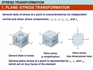
Chapter 3 Finite Element Method for Plane Stress and Plane Strain Problems (plane problems). 第三章 有限单元法解平面问题. Introduction-1. The finite element method is an extension of the analysis techniques (matrix method) of structures analysis. 有限元法结构分析技术的扩充。

Chapter 3 Finite Element Method for Plane Stress and Plane Strain Problems (plane problems)
E N D
Presentation Transcript
Chapter 3 Finite Element Method for Plane Stress and Plane Strain Problems (plane problems) 第三章 有限单元法解平面问题 Chapter 3
Introduction-1 • The finite element method is an extension of the analysis techniques (matrix method) of structures analysis. 有限元法结构分析技术的扩充。 • The finite element method was pioneered in the aircraft industry where there was an urgent need for accurate analysis of complex airframes. 有限元法首先应用于飞机工业。 Chapter 3
Introduction-2 • The availability of automatic digital computers from 1950 onwards contributed to the rapid development of matrix methods during this period. • Development of computer technology makes FEA to apply possibly. • ---Computer can solve n-dimension matrix. 从 1950年以后 数字计算机的出现使矩阵位移法迅速发展。 Chapter 3
Introduction-3 • The finite element method was developed rapidly from 1960 onwards and known in China from 1970 onwards and widely used in 1986 in China (Beijing university by professor WU ----software SAP5). • 从 1960以后 有限元法迅速发展。 1970以后 传入我国。 Chapter 3
Introduction-4 • In a continuum structure , a corresponding natural subdivision does not exist , so that the continuum has to be artificially divided into a number of elements before the matrix method of analysis can be applied. 连续结构不存在自然的单元,须人为划分为单元 Chapter 3
divided into a number of elements Fig.1 Fig.2 Fig.3 Fig.4 Chapter 3
Introduction-5 • The artificial elements, which are termed ‘finite elements’ or discrete elements, are usually chosen to be either rectangular or triangular in shape of plane . Spatial units are usually Tetrahedron and hexahedron in shape. 单元通常取为三角形或矩形。空间单元通常为四面体和六面体。 Chapter 3
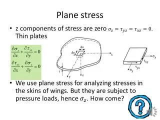
3.1Fundamental quantities and fundamental equations expressed by matrixPlane problem: Body force 体力: {Qv}=[X Y]T Surface force面力: {Qs}=[X Y]T Displacement 位移: {f}=[u v]T Strain 应变: {}=[x y rxy ]T Stress 应力: {}= [x y xy ]T Geometrical equations Physical equations virtual work equations Chapter 3
Geometrical Equation 几何方程 x u/x /x 0 u {}= y = v/y = 0 /y v =[L]{f} rxy u/y+v/x /y /x x /x 0 {}= y [L]= 0 /y {f} =[u v]T rxy /y /x {}==[L]{f} Chapter 3
Physical Equation for Plane Stress Problem 平面应力问题的物理方程 x x+y 1 0 x y = E/(1- 2) y+x = E/(1- 2) 1 0 y xy rxy(1-)/2 0 0 (1-)/2 rxy x 1 0 x {}= y [D] = E/(1- 2) 1 0 {}= y xy 0 0 (1-)/2 rxy {}= [D] {} Chapter 3
Virtual Work Equation 虚功方程 State 1: {Qv}=[X Y]T {Qs}=[X Y]T {}= [x y xy ]T State 2: {f*}=[u* v*]T {*}=[L] {f*} Virtual equation {f*}T{Qv}dx dy t+ {f*}T{Qs}ds t = {*}T{}dx dy t 注: {f*}T{Qv} =[ u* v*] X=X u*+Y v* Y {*}T {} =[x *y* rxy*] x = x x*+ y y* + xy rxy* y xy Chapter 3
3.2 Basic Concepts about Finite Element Method Computational model of FEM method • 1.The continuum structure is idealized as a structure consisting of a number of individual elements connected only at nodal points. 连续的结构理想化为仅由在结点相连的单元组成。 Chapter 3
2.Displacement boundary: place a bar support at the node where displacement is zero. 位移边界:结点位移为零处,设置连杆. • 3. The system of external loads acting on the actual structure has to be replaced by an equivalent system of forces concentrated at the element nodes.This can be done by using the principle of virtual work and equating the work done by the actual loads to the work done by the equivalent nodal loads. 外力按静力等效的原则移置到结点上 Chapter 3
About Discretization 1 • In reality Elements are connected together along their common boundaries. Here it is assumed that these elements are only interconnected at their nodes. 实际:单元间相连----假定:只结点相连 Chapter 3
About Discretization 2 • However,in the finite element method, the individual elements are constrained to deform in specific patterns. 然而,单元变形按指定模式. Chapter 3
About Discretization 3 • Hence, although continuity is only specified at the nodal points, the choice of a suitable displacement pattern for the elements can lead to the satisfaction of some,if not all,of the continuity requirements along the sides of adjacent elements. 位移模式使相连单元位移连续得某些满足 Chapter 3
About Discretization 4 • Hence, as stated by Clough, ‘finite elements are not merely pieces cut from the original structure, but are special types of elastic elements constrained to deform in specific patterns such that the overall continuity of the assemblage tends to be maintained. Chapter 3
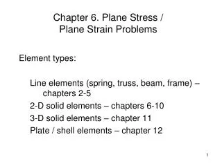
3.3 Displacement pattern and convergence criteria3.3 位移模式和收敛性 Element with nodes numbered Fig. 1 shows the typical triangular element with nodes △ijm numbered in an anti-clockwise order. Y m 图1为一典型的三角形单元, i 结点 ijm 逆钟向编号--x正向到 j y正向。 Fig..1 x e Chapter 3
Triangular element of plane problem e Chapter 3
Displacement pattern The displacement representation is given by the two linear polynomials with six constants 位移用有6个常数的线性多项式表示 u=1+ 2x+ 3y (1) v=4+ 5x+ 6y (2) Chapter 3
Displacement continuity Since these displacements are both linear in x and y , displacement continuity is ensured along the interface between adjoining elements for any identical nodal displacement.因为位移在单元上均为线性,相邻单元交界面上的位移连续性因同一结点位移相同而得到保证。 Chapter 3
To obtain 1 2 3 4 5 6 u=1+ 2x+ 3y (1) v=4+ 5x+ 6y (2) Substitution of the nodal coordinates into equation (1)(2) yields: 结点坐标代入方程(1) (2)得: Chapter 3
To obtain 1 2 3 4 5 6 Left of the three equations can be obtained : The above expression is ensured when the node ijm are in an anti-clockwise order. (Δ--area of triangle ijm 单元面积) Chapter 3
To obtain u ,v Resulting from processingcan be obtained: Among them: (i,j,m take turns ) ai,bi,ci etc. are constants, They are associated with point ijm’s coordinates . Chapter 3
To obtain u ,v In the same way : Suppose let: (i,j,m take turns ) Chapter 3
To obtain displacement Displacement mode u and v can be written as: Written in matrix form: Matrix [N] is called the shape function matrix. I is unit matrix. Chapter 3
To obtain strain • Using of plane geometrical equations: We can solve strain components: Chapter 3
To obtain strain • Can be simply written as: Matrix [B] is called strain matrix. The [B] matrix is independent of the position within the element, and hence the strains are constant throughout it. 应变在单元中为常量。See page 26. Chapter 3
To obtain stress • According to physical equations: • {σ} =[D]{ε} • Then: • Suppose: • Obtained: [S] is called stress matrix. Chapter 3
To obtain stress [S] can be written as: Among them: [Si], [Sj] ,[Sm]are call Block matrix. Chapter 3
To obtain stress Plane stress problems elastic matrix [D] is: Plane strain problems elastic matrix [D] is : (i,j,m take turns ) Chapter 3
To obtain stress Plane strain problems elastic matrix [D] is: Plane strain problems elastic matrix [D] is : (i,j,m take turns ) Chapter 3
Convergence Criteria _收敛准则 • Criterion 1: The displacement function chosen should be such that it does not permit straining of an element to occur when the nodal displacements are caused by a rigid body displacement. • 准则1:位移模式必须反映单元的刚体位移。 Chapter 3
Convergence Criteria --2 • Criterion 2: The displacement function has to be taken so that the constant strain (constant first derivative) could be observed. • 准则2:位移模式必须反映单元的常量应变。 Chapter 3
Convergence Criteria --3 • Criterion 3: The displacement function should be so chosen that the strains at the interface between elements are finite (even though indeterminate and not equal). • 准则3:位移模式必须使单元公共边上的应变在不同单元中为常量。 Chapter 3
Further discussion about criteria--1准则的进一步讨论--1 • Criterion 3 implies a certain continuity of displacements between elements--------In the case of strains being defined by first derivative, the displacements only have to be continuous between elements. That is C0 continuity is sufficient Chapter 3
Further discussion about criteria--2准则的进一步讨论--2 • Criterion 3 implies a certain continuity of displacements between elements.--------In the plate and shell problems, the ‘ strains ’are defined by second derivatives of deflections, first derivatives of deflections have to be continuous between elements. Chapter 3
Further discussion about criteria-1,2 准则的进一步讨论-1,2 • 准则3意味着对单元间位移的连续性有一定要求。-----应变是位移的一阶导数的情况,例如弹性力学平面问题,仅要求单元之间位移连续。称为C0连续性。------板和壳问题,应变是位移的二阶导数,要求位移的一阶导数在单元间连续, C1 连续性。 Chapter 3
Further discussion about criteria--3 准则的进一步讨论--3 • Criterion 1 and 2 are necessary conditions. Criterion 3 is the sufficient condition. 准则1和2是收敛的必要条件, 准则3是充分条件。 Chapter 3
3.4 Stiffness matrix C.1 Element Nodal Force Matrix Element nodal forces are the internal forces between elements and nodes. It is considered positive or negative according as it acts in the positive or negative direction of the coordinate axis when it acts on the element. C.2 Nodal I,j,m virtual displacement: Chapter 3
Triangular element of plane problem e Chapter 3
Stiffness matrix C.2 The relation between the element nodal force and nodal displacements Isolate an element from the structure. Since body forces and surface forces are moved to the nodes, only element nodal forces are the external forces acting on the element. Impose an arbitrary virtual nodal displacement . The work done by the nodal forces is equal to the work done by the stresses. Chapter 3
Virtual displacement is {f*}: Virtual strain internal element is : Work done by the external force on the virtual displacement is: Work done by Stress on the virtual strain: Chapter 3
Stiffness of element Assuming the element’s thickness t is constant ,then: Element’s virtual work equation: Chapter 3
Since {*}e is arbitrary, we have: {R}e = [B]T[D][B]dx dy t {}e=[k] {}e [k]= [B]T[D][B]dx dy t = [B]T[D][B]Δt [k]-----element stiffness matrix. 单元劲度矩阵 (lowercase letter “k” capital letter “K” ) Chapter 3
The stiffness matrix of triangular element is expressed as: Chapter 3
Plane stress problem [k]e ( r = i、j、m;s = i、j、m take turns ) Chapter 3
Plane strain problem [k]e ( r = i、j、m;s = i、j、m take turns ) Chapter 3