DIGITAL SPREAD SPECTRUM SYSTEMS
DIGITAL SPREAD SPECTRUM SYSTEMS. ENG-737 Lecture 9. Wright State University James P. Stephens. MULTIPATH SCENARIO. TYPES OF FADING DUE TO MULTIPATH. Multipath - Delay Spread Flat Frequency selective Doppler (Frequency Dispersion) Fast Slow What is Coherence BW?

DIGITAL SPREAD SPECTRUM SYSTEMS
E N D
Presentation Transcript
DIGITAL SPREAD SPECTRUM SYSTEMS ENG-737 Lecture 9 Wright State University James P. Stephens
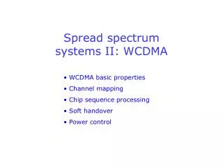
TYPES OF FADING DUE TO MULTIPATH • Multipath - Delay Spread • Flat • Frequency selective • Doppler (Frequency Dispersion) • Fast • Slow • What is Coherence BW? • CBW is the range of frequencies over which the channel passes all spectral component with equal gain and linear phase
MULTIPATH MITIGATION • Spread Spectrum (DS or FH) • Coding/Interleaving • Diversity ( at the transmitter) • Time • Space • Frequency • Equalization – FS • Rake - CDMA • OFDM • MC-CDMA
MULTICARRIER DIGITAL COMMUNICATIONS • Frequency Division Multiplexing (parallel) transmission dates back over a century • Telegraph messages could be carried over relatively wide bandwidth channel using separate carriers • Carriers must be spaced sufficiently apart to avoid overlap or adjacent channel interference (AM,FM, TV broadcast bands) • Instead of separate messages, different carriers can carry different bits of a single higher rate message • Such a parallel transmission system can be compared with a single higher rate serial scheme using the same channel • Parallel system more costly, but the serial will be susceptible to inter-symbol interference and other factors attributed to higher data rates
ORTHOGONAL FREQUENCY DIVISION MULTIPLEXING • 60’s – high frequency military systems (32 parallel data channels) • 70’s – Weinstein & Ebert applied DFT to parallel data system • 80’s – High speed modems & digital mobile communication. QAM and trellis coding implementation • 90’s – Wideband data communication over mobile radio FM channels OFDM is a special case of multicarrier transmission
OFDM CONCEPT a) Conventional multicarrier b) Orthogonal multicarrier To implement cross talk between subcarriers must be reduced.
OFDM SIGNAL GENERATION • A wideband single carrier is split into • Smaller narrow band subcarriers • Example of an OFDM symbol with • Four subcarriers • Each subcarrier has integer number of cycles in the interval T • Number of cycles between adjacent subcarrier differs by one Multipath delay spread is reduced by using OFDM subcarriers
d00 d1 I D F T D F T MOD Guard Time Bits Sym S(t) S(t) S(t) dN-1 S/P P/S S/P P/S d0 d1 dN-1 DEMOD R(t) Bits Sym Sym TRANSMITTER / RECEIVER
Gaurd OFDM symbol Cyclic prefix FFT integration time Guard time Integration time Direct Multipath GUARD TIME / CYCLIC PREFIX • Guard time is introduced for each OFDM symbol to completely reduce ISI. • .Generally guard time has no signal. To counter Inter Carrier Interference (ICI), OFDM symbols are cyclically extended in the guard time.
MODULATION / CODING • Modulation • PSK • QAM • Coding • Block Codes • Linear • cyclic • Convolution codes • Viterbi decoding • Interleaver
STRENGTH / WEAKNESS • Very effective in dealing with multipath • Receiver complexity minimal compared with single carrier system • Robust against narrow band interference • Sensitive to frequency / phase offsets • Relatively large peak to average power ratio, which tends to reduce RF power amplifier efficiency.
OFDM APPLICATIONS • Fixed/Wire line • Asymmetric Digital Subscriber Loop (ADSL) • Mobile/Radio • Digital Audio Broadcast (DAB) since 80’s • Digital Video Broadcast (DVB) • HIPERLAN II (wireless LAN) • 802.11 g • Wireless 1394 , extension of HIPERLAN II • 4G - ?
FOURIER BASED TRANSFORM DOMAIN SYSTEM • Method for implementing an interference-avoiding digital communications system • A “spectrally encoded” waveform • Waveform will exhibit Low Probability of Intercept (LPI) characteristics • Specify the waveform in the Transform Domain (Fourier) where non-desirable signal components can be ignored • Resulting signal avoids interference by adapting itself away from interference and jamming
INTRODUCTION • Historically, waveforms designed in time-domain and frequency domain characteristics accepted as consequence • All future waveforms may someday be spectrally encoded, i.e. designed in transform domain (TD) (i.e. frequency, time-scale, etc.) • Emphasis described here is on interference avoidance considerations • Others possible such as “Spectrally Modulated Spectrally Encoded (SMSE)”, “Cognitive Radio (CR)
Modulator Amplifier Multipliers RF Amp Mixer Detector Amplifier Output CONVENTIONAL COMMUNICATION SYSTEM Information Source Voice Data Video
FOURIER BASED TRANSFORM DOMAIN SYSTEM TDCS Transmitter Estimate Spectrum Establish Magnitudes TX X Memory Modulate FFT-1 Basis Function Data Random Phase
n Stage LFSR 1 0 0 1 0 0 1 0 1 . . . r Phase mapper taps {e jøi } Im[e jøi] 2r points RANDOM PHASE MAPPING • øi Î [ 0, 2p/2r,, 4p/2r,, . . . , 2p(2r-1)/2r] • i = 1, 2, . . . , N Re[e jøi]
ANTIPODAL • s1(t) = bf • s2(t) = -bf • Error performance in the presence of AWGN is identical to other antipodal signaling schemes • Benefits are when interferers are present • BINARY CSK • s1(t) = bf • s2(t) = s1((t - T/2))T • Cyclically time shifted version of the basis function • 3-dB performance loss compared to antipodal • m-ary signaling schemes are possible MODULATION TECHNIQUES Others are possible
SYNCHRONIZATION • Must align receiver’s locally generated basis function with transmitted basis function • Match filter or correlator structures are possible • In CSK, the waveform must be synchronized to the symbol period before demodulation can be accomplished • In an m-ary CSK, a correlation peak will appear on one of the m time slots in the periodic correlation • Initial acquisition would be aided by coded bit patterns that aid receiver in determining placement of symbol slots.
T ó õ X ( )dt Data Decision Rule FFT-1 Conjugate Spectrum Magnitude X Random Phase Local BF reference FOURIER BASED TRANSFORM DOMAIN SYSTEM TDCS Receiver
PERFORMANCE ISSUES • TDCS transmitter/receiver must view same spectral environment, i.e. must yield identical basis function • Operational Scenario - Group of aircraft flying deep interdiction mission • Smoothing of the TD coefficients effects environment estimate • CDMA can be implemented by using orthogonal coding • Adaptability is an important feature in the design • Quantization effects must be considered or signal artifacts are generated
ADAPTIVE SYSTEM TIMING DIAGRAM • Made adaptive by periodically resampling the environment and generating a new basis function • Rate of resampling depends on how fast the environment is changing • Resampling impacts the time that the system is available for transmitting Ts = time to transmit data symbol TT = time to transmit n symbols To = time to sample environment Tp = time to process the samples TF = frame time, period at which system revisits the environment
DISCRETE COSINE DOMAIN • An alternative for generating basis functions • DCT replaces the complex exponential of the DFT with a cosine function that is not complex • DCT produces only spectrum amplitudes and does not contain phase information • Therefore, amplitudes are the only parameter which may be manipulated to produce basis function • Once sampled environment is “compressed” by DCT, frequencies are eliminated and remaining frequencies are used to generate the basis function
WAVELET DOMAIN • Wavelets and wavelet packets provide a fundamentally different basis for analyzing signals compared to Fourier • Generating a wavelet basis function is accomplished by examining the time-scale coefficients and using only those which do not contain the interference • Like DCT, wavelet domain yields only amplitudes, thus the PN code must manipulate amplitudes not phase • Difficulty is selecting appropriate wavelet family and scale level for characterizing the interference • May not be able to localize interference to a consistent set of time-scale coefficients
TDCS SUMMARY • Transform domain techniques are shown to implement an interference avoidance waveform • May be accomplished by the use of Fourier, discrete cosine, or wavelet basis function • May be implemented using a variety of modulation and synchronization techniques • Performance is dependent on accuracy of the estimate of the environment and quantization effects resulting from sampling and D/A conversions • To achieve adequate data throughput, the complex DSP operations require multiple processors with high-speed data exchanges that are expensive and currently not well suited for integration into portable radios.
MULTICARRIER CODE DIVISION MULTIPLE ACCESS (MC-CDMA) • There are many possible ways to interpret and implement MC-CDMA • One way is to consider combining direct sequence CDMA (DS-CDMA) and OFDM • Like OFDM, the MC-CDMA signal is made up of a series of equal amplitude subcarriers • Unlike OFDM, where each subcarrier transmits a different symbol, MC-CDMA transmits the same data symbol over each Nth subcarrier • MC-CDMA applies spreading in the frequency domain by mapping a different chip of the spreading sequence to an individual OFDM subcarrier • The CDMA feature added to OFDM suppresses the effect of frequency selective fading due to inter-chip interference
MC-CDMA WITH FREQUENCY SPREADING C1 TRANSMITTER x CN Input symbols IFFT x q1 C1 RECEIVER x x CN qN Output symbols Add FFT x x
COGNITIVE RADIO COGNITIVE RADIO: is defined as a communication system which has the ability to detect other users in the electromagnetic environment and dynamically alter power, frequency, modulation, coding, and other parameters to efficiently utilize vacant spectrum while avoiding interferenc
COGNITIVE RADIO • Technologies which expand spectrum efficiency using elements of space, time, and frequency diversity • An adaptive waveform which adapts to the changing electromagnetic environment and synthesizes waveform features in the frequency domain • Spectral coexistence with other applications is also considered and can be accomplished in both static and dynamic environments • Recent FCC survey showed that “on average” only 2% of allocated spectrum in the U.S. is actually in use at any given moment • To exploit unused spectrum more efficiently, CR adapts to rapidly changing environmental conditions while ensuring minimal interference • Software Defined Radio (SDR) proposed as hardware architecture for CR