OSI Model
OSI Model. Unit - 1. www.educlash.com. OSI Model. A network is a combination of hardware and software that sends data from one location to another.

OSI Model
E N D
Presentation Transcript
OSI Model Unit - 1 www.educlash.com
OSI Model • A network is a combination of hardware and software that sends data from one location to another. • The hardware consists of the physical equipment that carries signals from one point of the network to another. • The software consists of instruction sets that make possible the services that we expect from a network www.educlash.com
The OSI Model • Established in 1947, the International Standards Organization (ISO) is a multinational body dedicated to worldwide agreement on international standards. • An ISO standard that covers all aspects of network communications is the Open Systems Interconnection model. An open system is a set of protocols that allows any two different systems to communicate regardless of their underlying architecture. • The purpose of the OSI model is to show how to facilitate communication between different systems without requiring changes to the logic of the underlying hardware and software. • The OSI model is not a protocol; it is a model for understanding and designing a network architecture that is flexible, robust, and interoperable. • ISO is the organization. OSI is the model. The OSI model is a layered framework for the design of network systems that allows communication between all types of computer systems www.educlash.com
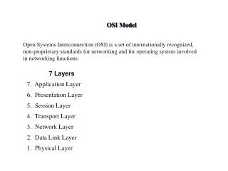
Seven layers www.educlash.com
Peer-to-Peer Processes www.educlash.com
Organization of the Layers • The seven layers can be thought of as belonging to three subgroups. • Layers 1, 2, and3-physical, data link, and network-are the network support layers; they deal with the physical aspects of moving data from one device to another (such as electrical specifications, physical connections, physical addressing, and transport timing and reliability). • Layers 5, 6, and 7-session, presentation, and application-can be thought of as the user support layers; they allow interoperability among unrelated software systems. • Layer 4, the transport layer, links the two subgroups and ensures that what the lower layers have transmitted is in a form that the upper layers can use. • The upper OSI layers are almost always implemented in software; lower layers are a combination of hardware and software, except for the physical layer, which is mostly hardware. www.educlash.com
An exchange using the OSI model www.educlash.com
Summary of Layers www.educlash.com
Physical Layer • The physical layer coordinates the functions required to carry a bit stream over a physical medium. • It deals with the mechanical and electrical specifications of the interface and transmission medium. • It also defines the procedures and functions that physical devices and interfaces have to perform for transmission to Occur. www.educlash.com
Physical Layer • The physical layer is also concerned with the following: • Physical characteristics of interfaces and medium: The physical layer defines the characteristics of the interface between the devices and the transmission medium. It also defines the type of transmission medium. • Representation of bits: The physical layer data consists of a stream of bits (sequence of 0s or 1s) with no interpretation. To be transmitted, bits must been coded into signals--electrical or optical. The physical layer defines the type of encoding (how 0s and 1s are changed to signals). • Data rate: The transmission rate-the number of bits sent each second-is also defined by the physical layer. In other words, the physical layer defines the duration of a bit, which is how long it lasts. • Synchronization of bits: The sender and receiver not only must use the same bit rate but also must be synchronized at the bit level. In other words, the sender and the receiver clocks must be synchronized. www.educlash.com
Physical Layer • Line configuration: The physical layer is concerned with the connection of devices to the media. In a point-to-point configuration, two devices are connected through a dedicated link. In a multipoint configuration, a link is shared among several devices. • Physical topology: The physical topology defines how devices are connected to make a network. Devices can be connected by using a mesh topology (every device is connected to every other device), a star topology (devices are connected through a central device), a ring topology (each device is connected to the next, forming a ring), a bus topology (every device is on a common link), or a hybrid topology (this is a combination of two or more topologies). • Transmission mode: The physical layer also defines the direction of transmission between two devices: simplex, half-duplex, or full-duplex. In simplex mode, only one device can send; the other can only receive. The simplex mode is a one-way communication. In the half-duplex mode, two devices can send and receive, but not at the same time. In a full-duplex (or simply duplex) mode, two devices can send and receive at the same time. www.educlash.com
Data Link Layer • The data link layer transforms the physical layer, a raw transmission facility, to a reliable link. It makes the physical layer appear error-free to the upper layer (network layer). www.educlash.com
Data Link Layer • Other responsibilities of the data link layer include the following: • Framing: The data link layer divides the stream of bits received from the network layer into manageable data units called frames. • Physical addressing: If frames are to be distributed to different systems on the network, the data link layer adds a header to the frame to define the sender and/or receiver of the frame. If the frame is intended for a system outside the sender's network, the receiver address is the address of the device that connects the network to the next one. • Flow control: If the rate at which the data are absorbed by the receiver is less than the rate at which data are produced in the sender, the data link layer imposes a flow control mechanism to avoid overwhelming the receiver. www.educlash.com
Data Link Layer • Error control: The data link layer adds reliability to the physical layer by adding mechanisms to detect and retransmit damaged or lost frames. It also uses a mechanism to recognize duplicate frames. Error control is normally achieved through a trailer added to the end of the frame. • Access control: When two or more devices are connected to the same link, data link layer protocols are necessary to determine which device has control over the link at any given time www.educlash.com
Network Layer • The network layer is responsible for the source-to-destination delivery of a packet, possibly across multiple networks (links). • Whereas the data link layer oversees the delivery of the packet between two systems on the same network (links), the network layer ensures that each packet gets from its point of origin to its final destination. • If two systems are connected to the same link, there is usually no need for a network layer. However, if the two systems are attached to different networks (links) with connecting devices between the networks (links), there is often a need for the network layer to accomplish source-to-destination delivery www.educlash.com
Responsibilities of the network layer • Logical addressing: • The physical addressing implemented by the data link layer handles the addressing problem locally. If a packet passes the network boundary, we need another addressing system to help distinguish the source and destination systems. The network layer adds a header to the packet coming from the upper layer that, among other things, includes the logical addresses of the sender and receiver. • Routing: • When independent networks or links are connected to create internetworks (network of networks) or a large network, the connecting devices (called routers or switches)route or switch the packets to their final destination. One of the functions of the network layer is to provide this mechanism. www.educlash.com
Network Layer www.educlash.com
Transport Layer • The transport layer is responsible for process-to-process delivery of the entire message. A process is an application program running on a host. • Whereas the network layer oversees source-to-destination delivery of individual packets, it does not recognize any relationship between those packets. • It treats each one independently, as though each piece belonged to a separate message, whether or not it does. • The transport layer, on the other hand, ensures that the whole message arrives intact and in order, overseeing both error control and flow control at the source-to-destination level. www.educlash.com
Working of Transport Layer www.educlash.com
Responsibilities of the transport layer • Service-point addressing: • Computers often run several programs at the same time. For this reason, source-to-destination delivery means delivery not only from one computer to the next but also from a specific process (running program) on one computer to a specific process (running program) on the other. The transport layer header must therefore include a type of address called a service-point address (or port address). The network layer gets each packet to the correct computer; the transport layer gets the entire message to the correct process on that computer. • Segmentation and reassembly: • A message is divided into transmittable segments, with each segment containing a sequence number. These numbers enable the transport layer to reassemble the message correctly upon arriving at the destination and to identify and replace packets that were lost in transmission. www.educlash.com
Responsibilities of the transport layer • Connection control: • The transport layer can be either connectionless or connection oriented. A connectionless transport layer treats each segment as an independent packet and delivers it to the transport layer at the destination machine. A connection oriented transport layer makes a connection with the transport layer at the destination machine first before delivering the packets. After all the data are transferred, the connection is terminated. • Flow control: • Like the data link layer, the transport layer is responsible for flow control. However, flow control at this layer is performed end to end rather than across a single link. • Error control: • Like the data link layer, the transport layer is responsible for error control. However, error control at this layer is performed process-to-process rather than across a single link. The sending transport layer makes sure that the entire message arrives at the receiving transport layer without error (damage, loss, or duplication). Error correction is usually achieved through retransmission. www.educlash.com
Transport Layer www.educlash.com
Session Layer • The services provided by the first three layers (physical, data link, and network) are not sufficient for some processes. • The session layer is the network dialog controller. It establishes, maintains, and synchronizes the interaction among communicating systems. www.educlash.com
Responsibilities of the session layer • Dialog control: • The session layer allows two systems to enter into a dialog. It allows the communication between two processes to take place in either half duplex (one way at a time) or full-duplex (two ways at a time) mode. • Synchronization: • The session layer allows a process to add checkpoints, or synchronization points, to a stream of data. For example, if a system is sending a file of 2000 pages, it is advisable to insert checkpoints after every 100 pages to ensure that each 100-page unit is received and acknowledged independently. In this case, if a crash happens during the transmission of page 523, the only pages that need to be resent after system recovery are pages 501 to 523. Pages previous to 501 need not be resent www.educlash.com
Presentation Layer • The presentation layer is concerned with the syntax and semantics of the information exchanged between two systems www.educlash.com
Responsibilities of the presentation layer • Translation: • The processes (running programs) in two systems are usually exchanging information in the form of character strings, numbers, and so on. The information must be changed to bit streams before being transmitted. Because different computers use different encoding systems, the presentation layer is responsible for interoperability between these different encoding methods. The presentation layer at the sender changes the information from its sender-dependent format into a common format. The presentation layer at the receiving machine changes the common format into its receiver-dependent format. • Encryption: • To carry sensitive information, a system must be able to ensure privacy. Encryption means that the sender transforms the original information to another form and sends the resulting message out over the network. Decryption reverses the original process to transform the message back to its original form. www.educlash.com
Responsibilities of the presentation layer • Compression: • Data compression reduces the number of bits contained in the information. Data compression becomes particularly important in the transmission of multimedia such as text, audio, and video. www.educlash.com
Application Layer • The application layer enables the user, whether human or software, to access the network. It provides user interfaces and support for services such as electronic mail, remote file access and transfer, shared database management, and other types of distributed information services. www.educlash.com
Services provided by the application layer • Network virtual terminal: • A network virtual terminal is a software version of a physical terminal, and it allows a user to log on to a remote host. To do so, the application creates a software emulation of a terminal at the remote host. The user's computer talks to the software terminal which, in turn, talks to the host, and vice versa. The remote host believes it is communicating with one of its own terminals and allows the user to log on. • File transfer, access, and management: • This application allows a user to access files in a remote host (to make changes or read data), to retrieve files from a remote computer for use in the local computer, and to manage or control files in a remote computer locally. www.educlash.com
Services provided by the application layer • Mail services: • This application provides the basis for e-mail forwarding and storage. • Directory services: • This application provides distributed database sources and access for global information about various objects and services www.educlash.com
TCP/IP Protocol Suite • The TCP/IP protocol suite was developed prior to the OSI model. Therefore, the layers in the TCP/IP protocol suite do not exactly match those in the OSI model. • The original TCP/IP protocol suite was defined as having four layers: host-to-network, internet, transport, and application. However, when TCP/IP is compared to OSI, we can say that the host-to-network layer is equivalent to the combination of the physical and data link layers. • The internet layer is equivalent to the network layer, and the application layer is roughly doing the job of the session, presentation, and application layers with the transport layer in TCP/IP taking care of part of the duties of the session layer. www.educlash.com
TCP/IP Protocol Suite vs OSI www.educlash.com
Layers in TCP/IP • Physical and Data Link Layers • Network Layer • Transport Layer • Application Layer www.educlash.com
Physical and Data Link Layers • At the physical and data link layers, TCP/IP does not define any specific protocol. It supports all the standard and proprietary protocols. A network in a TCP/IP internetwork can be a local-area network or a wide-area network. www.educlash.com
Network Layer • At the network layer (or, more accurately, the internetwork layer), TCP/IP supports the Internetworking Protocol. IP, in turn, uses four supporting protocols: ARP, RARP, ICMP, and IGMP. • Internetworking Protocol (IP): • The Internetworking Protocol (IP) is the transmission mechanism used by the TCP/IP protocols. It is an unreliable and connectionless protocol-a best-effort delivery service. The term best effort means that IP provides no error checking or tracking. IP assumes the unreliability of the underlying layers and does its best to get a transmission through to its destination, but with no guarantees. • IP transports data in packets called datagrams, each of which is transported separately. Datagrams can travel along different routes and can arrive out of sequence or be duplicated. IP does not keep track of the routes and has no facility for reordering datagrams once they arrive at their destination. www.educlash.com
Network Layer • The limited functionality of IP should not be considered a weakness, however. IP provides bare-bones transmission functions that free the user to add only those facilities necessary for a given application and thereby allows for maximum efficiency. • Address Resolution Protocol: • The Address Resolution Protocol (ARP) is used to associate a logical address with a physical address. On a typical physical network, such as a LAN, each device on a link is identified by a physical or station address, usually imprinted on the network interface card (NIC). ARP is used to find the physical address of the node when its Internet address is known. • Reverse Address Resolution Protocol: • The Reverse Address Resolution Protocol (RARP) allows a host to discover its Internet address when it knows only its physical address. It is used when a computer is connected to a network for the first time or when a diskless computer is booted. www.educlash.com
Network Layer • Internet Control Message Protocol • The Internet Control Message Protocol (ICMP) is a mechanism used by hosts and gateways to send notification of datagram problems back to the sender. ICMP sends query and error reporting messages. • Internet Group Message Protocol • The Internet Group Message Protocol (IGMP) is used to facilitate the simultaneous transmission of a message to a group of recipients www.educlash.com
Transport Layer • User Datagram Protocol • The User Datagram Protocol (UDP) is the simpler of the two standard TCP/IP transport protocols. It is a process-to-process protocol that adds only port addresses, checksum error control, and length information to the data from the upper layer. • Transmission Control Protocol • The Transmission Control Protocol (TCP) provides full transport-layer services to applications. TCP is a reliable stream transport protocol. The term stream, in this context, means connection-oriented: A connection must be established between both ends of a transmission before either can transmit data. At the sending end of each transmission, TCP divides a stream of data into smaller units called segments. • Each segment includes a sequence number for reordering after receipt, together with an acknowledgment number for the segments received. Segments are carried across the internet inside of IP datagrams. At the receiving end, TCP collects each datagram as it comes in and reorders the transmission based on sequence numbers. www.educlash.com
Transport Layer • Stream Control Transmission Protocol • The Stream Control Transmission Protocol (SCTP) provides support for newer applications such as voice over the Internet. It is a transport layer protocol that combines the best features of UDP and TCP. www.educlash.com
Application Layer • The application layer in TCP/IP is equivalent to the combined session, presentation, and application layers in the OSI model. Many protocols are defined at this layer. www.educlash.com
IPv4 Address www.educlash.com
What is IPv4 address? • An IPv4 address is a 32-bit address that uniquely and universally defines the connection of a device (for example, a computer or a router) to the Internet.IPv4 addresses are unique. • They are unique in the sense that each address defines one, and only one, connection to the Internet. • Two devices on the Internet can never have the same address at the same time. • On the other hand, if a device operating at the network layer has m connections to the Internet, it needs to have m addresses. • The IPv4 addresses are universal in the sense that the addressing system must be accepted by any host that wants to be connected to the Internet. www.educlash.com
Address Space • A protocol such as IPv4 that defines addresses has an address space. An address space is the total number of addresses used by the protocol. If a protocol uses N bits to define an address, the address space is 2Nbecause each bit can have two different values (0 or 1) and N bits can have 2Nvalues. • IPv4 uses 32-bit addresses, which means that the address space is 232 or 4,294,967,296 (more than 4 billion). This means that, theoretically, if there were no restrictions, more than 4 billion devices could be connected to the Internet www.educlash.com
Notations • There are two prevalent notations to show an IPv4 address: binary notation and dotted decimal notation. • Binary Notation • In binary notation, the IPv4 address is displayed as 32 bits. Each octet is often referred to as a byte. So it is common to hear an IPv4 address referred to as a 32-bit address or a 4-byte address. The following is an example of an • IPv4 address in binary notation: 01110101 10010101 00011101 00000010 www.educlash.com
Notations • Dotted-Decimal Notation • To make the IPv4 address more compact and easier to read, Internet addresses are usually written in decimal form with a decimal point (dot) separating the bytes. The following is the dotted decimal notation of the above address: 117.149.29.2 www.educlash.com
Notations: www.educlash.com
Classful Addressing • IPv4 addressing, at its inception, used the concept of classes. This architecture is called classful addressing. This scheme is becoming obsolete. • In classful addressing, the address space is divided into five classes: A, B, C, D, and E. • Each class occupies some part of the address space. We can find the class of an address when given the address in binary notation or dotted-decimal notation. • If the address is given in binary notation, the first few bits can immediately tell us the class of the address. • If the address is given in decimal-dotted notation, the first byte defines the class. www.educlash.com
Classfull Addressing www.educlash.com
Classes and Blocks www.educlash.com
Netid and Hostid • In classful addressing, an IP address in class A, B, or C is divided into netid and hostid. These parts are of varying lengths, depending on the class of the address. Note that the concept does not apply to classes D and E. • In class A, one byte defines the netid and three bytes define the hostid. • In class B, two bytes define the netid and two bytes define the hostid. • In class C, three bytes define the netid and one byte defines the hostid. www.educlash.com