Review of MAC protocols
410 likes | 646 Vues
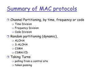
Review of MAC protocols. channel partitioning, by time, frequency or code Time Division, Frequency Division random access (dynamic), ALOHA, S-ALOHA, CSMA, CSMA/CD carrier sensing: easy in some technologies (wire), hard in others (wireless) CSMA/CD used in Ethernet CSMA/CA used in 802.11

Review of MAC protocols
E N D
Presentation Transcript
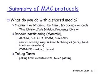
Review of MAC protocols • channel partitioning, by time, frequency or code • Time Division, Frequency Division • random access (dynamic), • ALOHA, S-ALOHA, CSMA, CSMA/CD • carrier sensing: easy in some technologies (wire), hard in others (wireless) • CSMA/CD used in Ethernet • CSMA/CA used in 802.11 • taking turns • polling from central site, token passing • Bluetooth, FDDI, IBM Token Ring Data Link Layer
Assumptions: all frames same size time divided into equal size slots (time to transmit 1 frame) nodes start to transmit only slot beginning nodes are synchronized if 2 or more nodes transmit in slot, all nodes detect collision Operation: when node obtains fresh frame, transmits in next slot if no collision: node can send new frame in next slot if collision: node retransmits frame in each subsequent slot with prob. p until success Slotted ALOHA Data Link Layer
Pros single active node can continuously transmit at full rate of channel highly decentralized: only slots in nodes need to be in sync nodes may be able to detect collision in less than time to transmit packet simple Cons collisions, wasting slots idle slots clock synchronization Slotted ALOHA Data Link Layer
suppose: N nodes with many frames to send, each transmits in slot with probability p prob that given node has success in a slot = p(1-p)N-1 prob that any node has a success = Np(1-p)N-1 max efficiency: find p* that maximizes Np(1-p)N-1 for many nodes, take limit of Np*(1-p*)N-1 as N goes to infinity, gives: Max efficiency = 1/e = .37 Slotted Aloha efficiency Efficiency : long-run fraction of successful slots (many nodes, all with many frames to send) At best: channel used for useful transmissions 37% of time! ! Data Link Layer
Pure (unslotted) ALOHA • unslotted Aloha: simpler, no synchronization • when frame first arrives • transmit immediately • collision probability increases: • frame sent at t0 collides with other frames sent in [t0-1,t0+1] Data Link Layer
Pure Aloha efficiency P(success by given node) = P(node transmits) . P(no other node transmits in [p0-1,p0] . P(no other node transmits in [p0-1,p0] = p . (1-p)N-1 . (1-p)N-1 = p . (1-p)2(N-1) … choosing optimum p and then letting n -> infty ... = 1/(2e) = .18 even worse than slotted Aloha! Data Link Layer
Ethernet “dominant” wired LAN technology: • cheap $20 for NIC • first widely used LAN technology • simpler, cheaper than token LANs and ATM • kept up with speed race: 10 Mbps – 10 Gbps Metcalfe’s Ethernet sketch Data Link Layer
Star topology • bus topology popular through mid 90s • all nodes in same collision domain (can collide with each other) • today: star topology prevails • active switch in center • each “spoke” runs a (separate) Ethernet protocol (nodes do not collide with each other) switch bus: coaxial cable star Data Link Layer
Ethernet Frame Structure Sending adapter encapsulates IP datagram (or other network layer protocol packet) in Ethernet frame Preamble: • 7 bytes with pattern 10101010 followed by one byte with pattern 10101011 • used to synchronize receiver, sender clock rates Data Link Layer
Ethernet Frame Structure (more) • Addresses: 6 bytes • if adapter receives frame with matching destination address, or with broadcast address (e.g. ARP packet), it passes data in frame to network layer protocol • otherwise, adapter discards frame • Type: indicates higher layer protocol (mostly IP but others possible, e.g., Novell IPX, AppleTalk) • CRC: checked at receiver, if error is detected, frame is dropped Data Link Layer
Ethernet: Unreliable, connectionless • connectionless: No handshaking between sending and receiving NICs • unreliable: receiving NIC doesn’t send acks or nacks to sending NIC • stream of datagrams passed to network layer can have gaps (missing datagrams) • gaps will be filled if app is using TCP • otherwise, app will see gaps • Ethernet’s MAC protocol: unslotted CSMA/CD Data Link Layer
1. NIC receives datagram from network layer, creates frame 2. If NIC senses channel idle, starts frame transmission If NIC senses channel busy, waits until channel idle, then transmits 3. If NIC transmits entire frame without detecting another transmission, NIC is done with frame ! 4. If NIC detects another transmission while transmitting, aborts and sends jam signal 5. After aborting, NIC enters exponential backoff: after mth collision, NIC chooses K at random from {0,1,2,…,2m-1}. NIC waits K·512 bit times, returns to Step 2 Ethernet CSMA/CD algorithm Data Link Layer
Jam Signal: make sure all other transmitters are aware of collision; 48 bits Bit time: .1 microsec for 10 Mbps Ethernet ;for K=1023, wait time is about 50 msec Exponential Backoff: Goal: adapt retransmission attempts to estimated current load heavy load: random wait will be longer first collision: choose K from {0,1}; delay is K· 512 bit transmission times after second collision: choose K from {0,1,2,3}… after ten collisions, choose K from {0,1,2,3,4,…,1023} Ethernet’s CSMA/CD (more) See/interact with Java applet on AWL Web site: highly recommended ! Data Link Layer
CSMA/CD efficiency • Tprop = max propagation delay for signal energy between 2 nodes in LAN • ttrans = time to transmit max-size frame • efficiency goes to 1 • as tprop goes to 0 • as ttrans goes to infinity • better performance than ALOHA: and simple, cheap, decentralized! Data Link Layer
application transport network link physical fiber physical layer copper (twister pair) physical layer 802.3 Ethernet Standards: Link & Physical Layers • many different Ethernet standards • common MAC protocol and frame format • different speeds: 2 Mbps, 10 Mbps, 100 Mbps, 1Gbps, 10G bps • different physical layer media: fiber, cable MAC protocol and frame format 100BASE-T2 100BASE-FX 100BASE-TX 100BASE-BX 100BASE-SX 100BASE-T4 Data Link Layer
twisted pair hub Hubs … physical-layer (“dumb”) repeaters: • bits coming in one link go out all other links at same rate • all nodes connected to hub can collide with one another • no frame buffering • no CSMA/CD at hub: host NICs detect collisions Data Link Layer
Switch • link-layer device: smarter than hubs, take active role • store, forward Ethernet frames • examine incoming frame’s MAC address, selectively forward frame to one-or-more outgoing links when frame is to be forwarded on segment, uses CSMA/CD to access segment • transparent • hosts are unaware of presence of switches • plug-and-play, self-learning • switches do not need to be configured Data Link Layer
Switch: allows multiple simultaneous transmissions A • hosts have dedicated, direct connection to switch • switches buffer packets • Ethernet protocol used on each incoming link, but no collisions; full duplex • each link is its own collision domain • switching:A-to-A’ and B-to-B’ simultaneously, without collisions • not possible with dumb hub C’ B 1 2 3 6 4 5 C B’ A’ switch with six interfaces (1,2,3,4,5,6) Data Link Layer
Switch Table A • Q: how does switch know that A’ reachable via interface 4, B’ reachable via interface 5? • A: each switch has a switch table, each entry: • (MAC address of host, interface to reach host, time stamp) • looks like a routing table! • Q: how are entries created, maintained in switch table? • something like a routing protocol? C’ B 1 2 3 6 4 5 C B’ A’ switch with six interfaces (1,2,3,4,5,6) Data Link Layer
Source: A Dest: A’ MAC addrinterface TTL 60 1 A A A’ Switch: self-learning A • switchlearns which hosts can be reached through which interfaces • when frame received, switch “learns” location of sender: incoming LAN segment • records sender/location pair in switch table C’ B 1 2 3 6 4 5 C B’ A’ Switch table (initially empty) Data Link Layer
Switch: frame filtering/forwarding When frame received: 1. record link associated with sending host 2. index switch table using MAC dest address 3. ifentry found for destinationthen { ifdest on segment from which frame arrivedthen drop the frame else forward the frame on interface indicated } else flood forward on all but the interface on which the frame arrived Data Link Layer
Source: A Dest: A’ A’ A MAC addrinterface TTL 60 60 1 4 A A’ A A’ A A’ A A’ A A’ A A’ A A’ Self-learning, forwarding: example A • frame destination unknown: C’ B 1 2 3 flood 6 4 5 • destination A location known: C selective send B’ A’ Switch table (initially empty) Data Link Layer
network link physical link physical datagram datagram frame frame frame Switches vs. Routers application transport network link physical • both store-and-forward devices • routers: network-layer devices (examine network-layer headers) • switches are link-layer devices (examine link-layer headers) • routers maintain routing tables, implement routing algorithms • switches maintain switch tables, implement filtering, learning algorithms switch application transport network link physical Data Link Layer
Point to Point Data Link Control • one sender, one receiver, one link: easier than broadcast link: • no Media Access Control • no need for explicit MAC addressing • e.g., dialup link, ISDN line • popular point-to-point DLC protocols: • PPP (point-to-point protocol) • HDLC: High level data link control (Data link used to be considered “high layer” in protocol stack!) Data Link Layer
PPP Design Requirements [RFC 1557] • packet framing: encapsulation of network-layer datagram in data link frame • carry network layer data of any network layer protocol (not just IP) at same time • ability to demultiplex upwards • bit transparency: must carry any bit pattern in the data field • error detection (no correction) • connection liveness: detect, signal link failure to network layer • network layer address negotiation: endpoint can learn/configure each other’s network address Data Link Layer
PPP non-requirements • no error correction/recovery • no flow control • out of order delivery OK • no need to support multipoint links (e.g., polling) Error recovery, flow control, data re-ordering all relegated to higher layers! Data Link Layer
PPP Data Frame • Flag: delimiter (framing) • Address: does nothing (only one option) • Control: does nothing; in the future possible multiple control fields • Protocol: upper layer protocol to which frame delivered (e.g., PPP-LCP, IP, IPCP, etc) Data Link Layer
PPP Data Frame • info: upper layer data being carried • check: cyclic redundancy check for error detection Data Link Layer
Asynchronous Transfer Mode: ATM • 1990’s/00 standard for high-speed (155Mbps to 622 Mbps and higher) Broadband Integrated Service Digital Network architecture • Goal:integrated, end-end transport of carry voice, video, data • meeting timing/QoS requirements of voice, video (versus Internet best-effort model) • “next generation” telephony: technical roots in telephone world • packet-switching (fixed length packets, called “cells”) using virtual circuits Data Link Layer
Multiprotocol label switching (MPLS) • initial goal: speed up IP forwarding by using fixed length label (instead of IP address) to do forwarding • borrowing ideas from Virtual Circuit (VC) approach • but IP datagram still keeps IP address! PPP or Ethernet header IP header remainder of link-layer frame MPLS header label Exp TTL S 5 1 3 20 Data Link Layer
MPLS capable routers • a.k.a. label-switched router • forwards packets to outgoing interface based only on label value (don’t inspect IP address) • MPLS forwarding table distinct from IP forwarding tables • signaling protocol needed to set up forwarding • RSVP-TE • forwarding possible along paths that IP alone would not allow (e.g., source-specific routing) !! • use MPLS for traffic engineering • must co-exist with IP-only routers Data Link Layer
in out out label label dest interface 10 6 A 1 12 9 D 0 in out out label label dest interface in out out label label dest interface 8 6 A 0 6 - A 0 MPLS forwarding tables in out out label label dest interface 10 A 0 12 D 0 8 A 1 R6 0 0 D 1 1 R3 R4 R5 0 0 A R2 R1 Data Link Layer
Synthesis: a day in the life of a web request • journey down protocol stack complete! • application, transport, network, link • putting-it-all-together: synthesis! • goal: identify, review, understand protocols (at all layers) involved in seemingly simple scenario: requesting www page • scenario: student attaches laptop to campus network, requests/receives www.google.com Data Link Layer
browser A day in the life: scenario DNS server Comcast network 68.80.0.0/13 school network 68.80.2.0/24 web page web server Google’s network 64.233.160.0/19 64.233.169.105 Data Link Layer
DHCP UDP IP Eth Phy DHCP UDP IP Eth Phy DHCP DHCP DHCP DHCP DHCP DHCP DHCP DHCP DHCP DHCP A day in the life… connecting to the Internet • connecting laptop needs to get its own IP address, addr of first-hop router, addr of DNS server: use DHCP • DHCP request encapsulatedin UDP, encapsulated in IP, encapsulated in 802.1 Ethernet router (runs DHCP) • Ethernet frame broadcast (dest: FFFFFFFFFFFF) on LAN, received at router running DHCP server • Ethernet demuxed to IP demuxed, UDP demuxed to DHCP Data Link Layer
DHCP UDP IP Eth Phy DHCP UDP IP Eth Phy DHCP DHCP DHCP DHCP DHCP DHCP DHCP DHCP DHCP A day in the life… connecting to the Internet • DHCP server formulates DHCP ACK containing client’s IP address, IP address of first-hop router for client, name & IP address of DNS server • encapsulation at DHCP server, frame forwarded (switch learning) through LAN, demultiplexing at client router (runs DHCP) • DHCP client receives DHCP ACK reply Client now has IP address, knows name & addr of DNS server, IP address of its first-hop router Data Link Layer
ARP ARP Eth Phy ARP query ARP reply DNS UDP IP Eth Phy DNS DNS DNS A day in the life… ARP (before DNS, before HTTP) • before sending HTTPrequest, need IP address of www.google.com:DNS • DNS query created, encapsulated in UDP, encapsulated in IP, encapsulated in Eth. In order to send frame to router, need MAC address of router interface: ARP • ARP query broadcast, received by router, which replies with ARP reply giving MAC address of router interface • client now knows MAC address of first hop router, so can now send frame containing DNS query Data Link Layer
DNS UDP IP Eth Phy DNS UDP IP Eth Phy DNS DNS DNS DNS DNS DNS DNS DNS DNS A day in the life… using DNS DNS server Comcast network 68.80.0.0/13 • IP datagram forwarded from campus network into comcast network, routed (tables created by RIP, OSPF, IS-IS and/or BGP routing protocols) to DNS server • IP datagram containing DNS query forwarded via LAN switch from client to 1st hop router • demuxed to DNS server • DNS server replies to client with IP address of www.google.com Data Link Layer
SYN SYN SYN SYN SYN SYN SYN HTTP TCP IP Eth Phy TCP IP Eth Phy HTTP SYNACK SYNACK SYNACK SYNACK SYNACK SYNACK SYNACK A day in the life… TCP connection carrying HTTP • to send HTTP request, client first opens TCP socket to web server • TCP SYN segment (step 1 in 3-way handshake) inter-domain routed to web server • web server responds with TCP SYNACK (step 2 in 3-way handshake) web server 64.233.169.105 • TCP connection established! Data Link Layer
HTTP TCP IP Eth Phy HTTP TCP IP Eth Phy HTTP HTTP HTTP HTTP HTTP HTTP HTTP HTTP HTTP HTTP HTTP HTTP HTTP HTTP A day in the life… HTTP request/reply • web page finally (!!!) displayed • HTTP request sent into TCP socket • IP datagram containing HTTP request routed to www.google.com • web server responds with HTTP reply (containing web page) web server • IP datagram containing HTTP reply routed back to client 64.233.169.105 Data Link Layer