Cathode Ray Tubes and their Uses.
330 likes | 804 Vues
Cathode Ray Tubes and their Uses. Thermionic Emission. Electrons flow in electron clouds in metals. The electrons easily leave the surface of hot metals – as they gain enough energy from the heat to overcome the attraction of the nuclei.

Cathode Ray Tubes and their Uses.
E N D
Presentation Transcript
Thermionic Emission • Electrons flow in electron clouds in metals. • The electrons easily leave the surface of hot metals – as they gain enough energy from the heat to overcome the attraction of the nuclei. • A stream of electrons leaving the surface of a hot metal is known as thermionic emission. • The stream of electrons are called cathode rays, since they are made up negative charges.
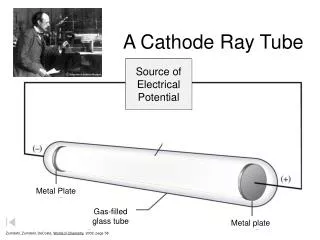
CATHODE RAY TUBES • Cathode rays are produced in glass tubes which contain gases at low pressure. • Cathode ray tubes contain a filament from which the electrons are emitted - (cathode). • Cathode ray tubes may also contain a heater filament which heats a separate cathode to emit electrons. • As electrons are move towards an anode they cause ionization of the gas. • The charged particles are accelerated toward the electrodes – positive ions to the cathode and electrons and negative ions to the anode. • This movement results in the formation of more ions.
Properties of Cathode Rays • Cathode rays travel in straight lines thus they cast a shadow on a screen – Maltese Cross experiment. • Cathode rays are deflected by a magnetic field. • Cathode rays are deflected by an electric field. • Cathode rays convey negative charges. • Cathode rays convey energy.
Maltese Cross Experiment Cathode rays travel in straight lines and so cast a shadow on a fluorescence screen.
Cathode Rays-deflected by Magnetic Field Since cathode rays are negatively charged and are flowing in a particular direction, (current flow) they generate a magnetic field. So another magnetic field causes deflection of the beam according to Fleming’s left hand rule.
Cathode rays-deflected by electric field Electrons from the hot cathode are accelerated toward an anode and emerges as a flat thin beam on a fluorescence screen. The deflection is towards the positive plate.
Cathode Rays Convey Negative Charges Cathode rays cause a build up of charges on the Faraday cylinder, which is indicated by a divergence of the electroscope. When tested, the electroscope was found to be negatively charged.
Cathode Rays Convey Energy Cathode rays pass the vanes of the paddle wheel and cause it to rotate towards the anode. The vanes become hot also, and gas particles around it become more energetic, causing more rotation.
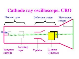
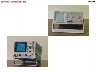
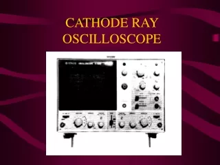
The Cathode Ray Oscilloscope The cathode ray oscilloscope is an instrument used for studying the current and voltage waveforms of various circuits.
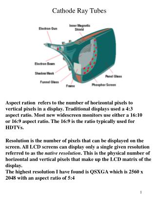
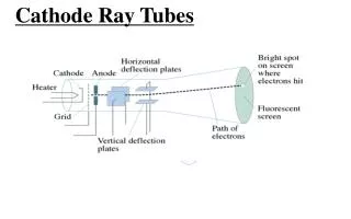
Cathode Ray Oscilloscope • The tube is made of glass and is a vacuum. • The glass must be strong enough to withstand the pressure difference. • The parts of a cathode ray tube are: • The electron gun-heater, cathode, grid. • Anodes • The deflection plates-Y plates and X plates. • The screen.
The Electron Gun • Heater: is used to heat the cathode so that electrons can stream off. • The grid: is an electrode fitted around thecathode. • The grid is usually made negatively charged with respect to the cathode. The grid controls the number of electrons in the a beam. The more negative the grid the more repulsion of electrons and the fewer electrons reach the anodes. • The number of electrons reaching the screen determines the brightness of the light emitted by the screen. The grid is therefore used as a brightness or brilliance control.
The Anodes • More than one anode is used to accelerate the electrons and focus them into a narrow beam. • The anodes are cylindrical and ring-like in shape. • The anodes become increasingly positive as the electrons pass through them.
Deflection Plates • A small voltage between the plates cause the beam to be deflected so that it traces out a pattern on the screen. • The y – plates arranged horizontally, above and below the beam, deflects the beam up and down the screen. i.e. vertical deflection. • The x – plates arranged vertically, to the left and right of the beam, deflects the beam across the screen. i.e. horizontal deflection - to the left and right.
The Screen • Quick changes in the voltage of the plates produce rapid deflections of the spot of light on the screen. • The trace is made continuous by: • 1. Persistence of vision- where the spot was a short time ago still lingers for a short time after it has passed. • 2. The screen is coated with phosphorous. Molecules of the phosphorous absorb energy from the electrons which strike it.
The Screen • This causes the electrons of the phosphorous the become excited and go to higher shells. • The then fall back to original shells, losing the energy as light. • This results inphosphorescence. • The screen is fitted with grids like a graph paper and calculations can be made using graphs traced out.
Using the Cathode Ray Oscilloscope • On/off, brilliance control: • Turns on the CRT and adjusts the brightness of the spot. • Shift controls: • x – shift control: moves the spot horizontally by applying a d.c. voltage to the x – deflection plates. • y – shift control: moves the the spot vertically by applying a d.c. voltage to the y – deflection plates.
Using The Cathode Ray Oscilloscope • Input terminals: • a pair of input terminals are provided because the CRO can be used to measure potential difference between two points in a circuit. Voltmeters are connected in parallel- so it needs two terminals. • The terminals may be labeled 1. high (or y- input) and 2. low (or earth) • The y- input causes an upwards deflection of the spot on the screen, when connected to the low. • Another terminal labeled x-input, can be used for a horizontal deflection when connected to the low. This is not used in simple applications.
Using The Cathode Ray Oscilloscope • The gain controls: • y – gain control is calibrated in volts per division and is used to select the scale for the y-axis of the graph on the screen. (for measuring voltage) • x-gain control is calibrated in milliseconds per division and is used to determine the time depending on the frequency of the input. (for a.c. wave form)
CRO As a Voltmeter -A d.c. voltage displaces the spot from one point to the next, since d.c. only goes in one direction. -An a.c. voltage, moving in both directions, results in vertical trace.
CRO As a Voltmeter The value of a d.c. voltage measurement is found by multiplying the number of divisions displaced by the spot (divisions) and the selected rangeon the y-gain control (V/division). d.c. No. ofy-gain voltage = divisions X setting moved
CRO As a Voltmeter The value of an a.c. voltage measurement is found by multiplying the length of the trace from zero (divisions) and the selected rangeon the y-gain control (V/division). peakNo. ofy-gain a.c. = divisions X setting voltagemoved
a)The time-base control • is set to100ms/division. • This means that the spot • will travel across the • screen (10divisions) once • every second. • Time to cross the screen • 10 divisions wide • = 10 divs X 100ms/div • = 1000 ms = 1s • 1 cycle per second = 1 Hz CRO Displaying Wave Forms
CRO Displaying Wave Forms b) The time-base control is set to 10ms/division. So The spot travels 10divisions in 10ms/divs X 10 divs =100ms = 0.1s i.e. 1 cycle in 0.1 s x cycle in 1.0 s 0.1 x = 1 x = 1/0.1 = 10 10 cycles in 1 second=10Hz
In c), d) and e) using a mains • step-down transformer, an accurate • 50 Hz a.c. voltage is applied. These • show how the display is affected • by selecting different time-base frequencies. • Time for 1 cycle = • 2ms/div x 10div = 20ms • 20ms = 20/1000 s = 0.02 s • 1 cycle = 0.02 s • x cycles= 1.0 s • 0.02x = 1 • x = 1/0.02 cycles • i.e. 50 cycles per second= 50 Hz CRO Displaying Wave Forms
d) Here the time base is set for 4 ms/div. This means that the time taken for 1 cycle is 4 ms/div x 10 divs = 40 ms 40 ms = 0.04 s 1 cycle takes 0.04 s X cycle takes 1.0 s 0.04 x = 1.0 x = 1.0/0.04 = 25 cycles per second This wave will cross the screen 25 times in one sec. CRO Displaying Wave Forms
CRO Displaying Wave Forms e) In this case a time-base of 1 ms/ div is chosen. Can you work out the frequency? Please do! f) and g) A half-wave rectified voltage is connected to the y-input. The output is d.c. The voltage does not become negative so the setting must be to d.c. and not to a.c.