Implication Graphs and Logic Testing
Explore the concept of implication graphs representing Boolean variables and their relations, transitive closure, logic testing for fault detection, and using partial implications. Learn from Vishwani D. Agrawal & James J. Danaher's research.

Implication Graphs and Logic Testing
E N D
Presentation Transcript
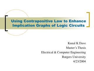
Implication Graphs and Logic Testing Vishwani D. Agrawal James J. Danaher Professor Dept. of ECE, Auburn University Auburn, AL 36849 vagrawal@eng.auburn.edu www.eng.auburn.edu/~vagrawal Joint research with: M. L. Bushnell, Rutgers University, Piscataway, NJ K. K. Dave, ATI Research, Yardley, PA Agrawal: Implication Graphs
Implication Graph • An implication graph (IG) represents the implication relations between pairs of Boolean variables. a b an implication contrapositive implication a b Agrawal: Implication Graphs
a c b Implication Graph of a Logic Gate c = ab Boolean false function:ab c = 0 ac + bc + abc = 0 a c b c a b • Chakradhar et al. -- IEEE-D&T, 1990 Agrawal: Implication Graphs
Global Implications and Transitive Closure a c b a c b Transitive closure edge c a b c ≡ 0 Agrawal: Implication Graphs
Transitive Closure • Transitive closure (TC) of a directed graph contains the same set of nodes as the original graph. • If there is a directed path from node a to b, then the transitive closure contains an edge from a to b. A Graph Transitive Closure a a b a b c d a 0 1 0 0 b 0 0 1 0 c 0 0 0 1 d 0 0 0 0 b a b c d a 0 1 11 b 0 0 1 1 c 0 0 0 1 d 0 0 0 0 d d c c A graph Agrawal: Implication Graphs
Transitive Closure: Warshall’s Algorithm procedureWarshall (varA : array[1…n, 1…n] of boolean; C : array[1…n, 1…n] of boolean); { Warshall makes A the transitive closure of C } var i, j, k : integer; begin fori := 1 tondo forj := 1 tondo A[i, j] := C[i, j]; fork := 1 tondo O(n3) fori := 1 tondo forj := 1 tondo if A[i, j] = false then A[i, j] := A[i, k] andA[k, j] end; { Warshall } S. Warshall, “A Theorem on Boolean Matrices,” J. ACM, vol. 9, no. 1, pp. 11-12, 1962. A. V. Aho, J. E. Hopcroft and J. D. Ullman, Data Structures and Algorithms, Reading, Massachusetts: Addison-Wesley, 1983, p. 213. Agrawal: Implication Graphs
Transitive Closure: Update Algorithm • Start constructing transitive closure (TC) by placing all nodes and no edges. This edge-less graph is its own TC. • Add edges to TC in any arbitrary order • For each edge i → j find • P : set of parent nodes of i • C : set of child nodes of j • Add edges {P, i } → {C, j } K. Dave, “Using Contrapositive Rule to Enhance the Implication Graphs of Logic Circuits,” Master’s Thesis, Rutgers University, Dept. of ECE, Piscataway, New Jersey, May 2004. Agrawal: Implication Graphs
Update Algorithm p2 p1 {P, i } Edges before i→ j is added i Edges after i→ j is added j {C, j } c1 Agrawal: Implication Graphs
a b c d Update Algorithm Example a b a b c d c d A directed graph a a a b b b c c c d d d Transitive closure Agrawal: Implication Graphs
Logic Testing: Stuck-at Fault • A type of fault, which causes a line to hold a constant logic value, irrespective of change of state at previous stages. • There are two types of stuck-at-faults: • Stuck-at-1 • Stuck-at-0 • Detection of a fault requires the fault to be activated and its effect observed at a primary output (PO). • Fault a s-a-1 is detectable, if following conditions are simultaneously satisfied: • a = 0 fault is activated • Oa = 1 “observability” is true Agrawal: Implication Graphs
OCb Oa = 0 OcOa + bOa + OcbOa = 0 Observability Variables Observability variable of a signal represents whether or not that signal is observable at a PO. It can be true or false. Oa Oc= 1 Oc a b Oa c b (PO) Ob Agrawal, Bushnell and Lin, “Redundancy Identification using Transitive Closure,” Proc.Asian Test Symp., 1996, pp. 5-9. Agrawal: Implication Graphs
Redundant Faults • A fault that has no test is called an untestable fault. • Any untestable fault in a combinational circuit is a redundant fault because it does not cause any change in the input/output logic function of the circuit. • Identification of redundant faults is useful because they can be removed • from testing consideration, or • from hardware • Fault a stuck-at-1 is redundant if • either a≡ 1 no controllability • or Oa ≡ 0 no observability • or a = 0 → Oa = 0no drivability • or Oa → a no drivability Agrawal: Implication Graphs
Od Oc Limitation of Implication Graph c a b c d a s-a-0 e s-a-0 b d Circuit with two redundant faults Implication graph (some nodes and edges not shown) Implication graph shows no implications of c and d on their observabilities. Agrawal: Implication Graphs
a c b Adding Partial Implications c = ab Boolean false function:ab c = 0 ac + bc + abc = 0 a c b Henftling and Wittmann, AEÜ, 1995 (Λ node) Λ Dave, Master’s Thesis, 2004 (V node) c a b Λ and V nodes represent partial implications V Agrawal: Implication Graphs
Od Oc Using Partial Implications c a b c d a s-a-0 e s-a-0 b d Circuit with two redundant faults Implication graph (some nodes and edges not shown) Implication Partial implication Transitive closure edge Agrawal: Implication Graphs
Another Example s-a-0 s-a-1 a c b s-a-0 e s-a-0 s-a-1 d Contrapositive of đ→ ē e a c d b Λ2 Λ1 Λ3 a e c d b e ≡ 0 Λ4 V1 V2 Agrawal: Implication Graphs
Results on ISCAS Circuits aSun SPARC5 CPU Sec. bSun SPARC2 CPU Sec. Agrawal: Implication Graphs
Referenced Methods • TRAN – ATPG • S. T. Chakradhar, V. D. Agrawal and S. G. Rothweiler, “A Transitive Closure Algorithm for Test Generation,” IEEE Trans. CAD, vol. 12, no. 7, pp. 1015-1028, July 1993. • FIRE – Implication analysis • M. A. Iyer and M. Abramovici, “FIRE: A Fault-Independent Combinational Redundancy Identification Algorithm,” IEEE Trans. VLSI Systems, vol. 4, no. 2, pp. 295-301, June 1996. • Implication Graph • V. J. Mehta, “Redundancy Identification in Logic Circuits using Extended Implication Graph and Stem Unobservability Theorems,” Master’s Thesis, Rutgers University, Dept. of ECE, New Brunswick, NJ, May 2003. • K. K. Dave, “Using Contrapositive Rule to Enhance the Implication Graphs of Logic Circuits,” Master’s Thesis, Rutgers University, Dept. of ECE, New Brunswick, NJ, May 2004. Agrawal: Implication Graphs
C1908: Unidentified Redundancies Redundant faults (s-a-1) 949 952 0/1 0 979 953 887 926 0 74 Total redundant faults = 7; identified = 5 Agrawal: Implication Graphs
C5315: Unidentified Redundancy Redundant fault (s-a-1) PI 1 0 0 0/1 0/1 1 1 PI 1 0/1 0/1 PO 0 0 0 1 1 1 1 1 Total redundant faults = 59; identified = 58 Agrawal: Implication Graphs
C5315: Continued . . . Redundant fault (s-a-1) PI 1 1 0/1 0/1 0/1 1 1 PI 0 0 0/1 PO 1 1 1 0 1 0 0 1 Agrawal: Implication Graphs
Conclusion • Partial implications improve fault-independent redundancy identification – present results are the best known. • Transitive closure computation run times are empirically linear in the number of nodes for benchmark circuits -- the known worst-case complexity is O(N3) for N nodes. • Update algorithm can efficiently compute transitive closure when implication graph has sparse connectivity. • Weakness of implication method: Observability of fanout stems. Recent work has shown that some unobservable fanout stems can be identified from transitive closure analysis. Observability of a has no direct relation to observabilities of b and c, but can be related to that of d b Dominator Reconvergent gate a d c Agrawal: Implication Graphs
Our Students • Srimat Chakradhar, NEC • Qing Lin, Sun Microsystems • Philip Stanley-Marbell, CMU Graduate Program • Vivek Gaur, Synopsys • Vishal Mehta, UCSB PhD Program • Kunal Dave, ATI Agrawal: Implication Graphs