Asynchronous Transfer Mode (ATM) Protocol Stack
220 likes | 242 Vues
Learn the essentials of ATM, its protocol stack, design decisions, VC approach, quality of service, and more to provide better services than best effort, suitable for both data and voice traffic.

Asynchronous Transfer Mode (ATM) Protocol Stack
E N D
Presentation Transcript
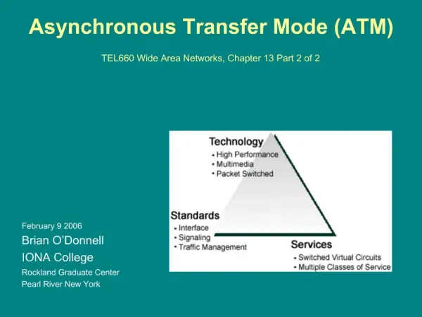
EE 122: Lecture 19(Asynchronous Transfer Mode - ATM) Ion Stoica Nov 13, 2001 (* based on some on-line slides of J. Kurose & K. Rose)
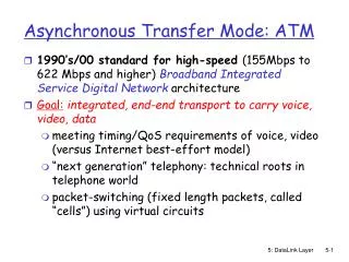
Goals • Provide better services than best-effort • Able to carry both data and voice (telephony) traffic • Can be implemented at very high speeds istoica@cs.berkeley.edu
ATM Protocol Stack • Physical layer • ATM layer: performs routing (similar in function to IP + data link layer) • ATM Adaptation Layer (AAL) – performs segmentation and reassembly, multiplexing (similar in function to the transport layer) Source Destination AAL AAL ATM ATM ATM Phys Phys Phys istoica@cs.berkeley.edu
Design Decisions • Fixed size packets – cells • Based on virtual circuit istoica@cs.berkeley.edu
Why Fixed Size? • Easier to implement high speed switches • Easier to do processing when the cell length is known in advance • Easier to implement parallel and pipeline solutions when the processing of all cells take the same time • A cell is in general much smaller than the maximum packet size • A high priority cell needs to wait less before being transmitted (a low priority cell will take less time to be transmitted than a packet of maximum size) • When the is empty, the first data bits are in general transmitted faster • Cell size: 48 byte payload + 5 byte header • A compromise between US (64 byte payload) and Europe (32 byte payload) istoica@cs.berkeley.edu
ATM Cell Header • VCI: virtual channel ID • will change from link to link through network • PT:Payload type (e.g. control cell versus data cell) • CLP: Cell Loss Priority bit • CLP = 1 implies low priority cell, can be discarded if congestion • HEC: Header Error Checksum • cyclic redundancy check istoica@cs.berkeley.edu
ATM Cell Header • First 4 bits in VCI – GFC (Generic Flow Control) • Local significance at the end-host • Arbitrate the access to the link if a shared medium is used to connect to ATM • GFC bits can be overwritten by the newtork istoica@cs.berkeley.edu
ATM VCs • Advantages of ATM VC approach: • QoS performance guarantee for connection mapped to VC (bandwidth, delay, delay jitter) • Drawbacks of ATM VC approach: • Inefficient support of datagram traffic • One VC between each source/dest pair) does not scale (N*2 connections needed) • VC introduces call setup latency, processing overhead for short lived connections istoica@cs.berkeley.edu
Virtual Circuit (VC) Forwarding • Each router maintains a routing table • A routing entry: (input port, input VCI, output port, output VCI); • VCI – Virtual Circuit Identifier • Upon a cell arrival at interface i • Input port uses i and the packet’s VCI v to find the routing entry (i, v, i’, v’) • Replaces v with v’ in the packet header • Forwards packet to output port I’ istoica@cs.berkeley.edu
1 11 5 7 VC Forwarding: Example in-VCI out-VCI out in … … … … in-VCI out-VCI out in 1 7 4 1 … … … … … … … … destination source 3 5 4 11 … … … … 1 1 2 2 1 1 3 3 2 2 4 4 3 3 4 4 1 1 2 2 3 3 4 4 in-VCI out-VCI out in … … … … 2 11 3 7 … … … … istoica@cs.berkeley.edu
Virtual Path Identifier (VPI) • ATM splits the VCI in two • 16 bits Virtual Path Identifier (VPI) • 8-12 bits VCI • Use to implement hierarchical routing • All VCI between two subnets share the same VPI • Backbone switches switch based on VPI • Switches in edge networks switch based on the entire VCI Backbone(Public) Network Virtual path Network A Network B istoica@cs.berkeley.edu
Virtual Path Identifier (VPI) • ATM splits the VCI in two • 16 bits Virtual Path Identifier (VPI) • 8-12 bits VCI • Use to implement hierarchical routing • All VCI between two subnets share the same VPI • Backbone switches switch based on VPI • Switches in edge networks switch based on the entire VPI Backbone(Public) Network Virtual path Network A Network B istoica@cs.berkeley.edu
ATM Adaptation Layer • Goal: allow existing protocols and applications to run on top of ATM • AAL is implemented only at endpoints • AAL has two sub-layers • Convergence Sub-layer (CS) • Segmentation and Reassembly (SAR) sub-layer • Usually CS adds • Common Part Convergence Sub-layer (CPCS) header and trailer • Checksum istoica@cs.berkeley.edu
AAL Structure Protocol Data Unit (PDU) • Example of AAL header information • Type (e.g., first cell, last cell in PDU) • Sequence # of the cell within PDU CPCS header PDU CPCS trailer ATM cell header AAL header Payload data <= 48 ATM cell trailer istoica@cs.berkeley.edu
ATM Quality of Service (QoS) • Constant bit rate (CBR) • Variable bit rate – real-time (VBR-rt) • Variable bit rate –non-real-time (VBE-nrt) • Available bit rate (ABR) • Unspecified bit rate (UBR) istoica@cs.berkeley.edu
ATM QoS (cont’d) • VBR-rt – similar to Guaranteed Service in Intserv • Traffic is specified by a token bucket, and the end-to-end delay is specified • CBR – very similar to VBR-rt, but the source is expected to send at a specified rate (e.g., telephony traffic) • Specified by a token-bucket with very small bucket, e.g., 1 cell • VBR-nrt – similar to the Controlled –load Service in Intserv • Traffic specified by token-bucket, but no hard delay guarantees istoica@cs.berkeley.edu
ATM QoS (cont’d) • UBR - similar to best-effort service, but • There can still be an admission control: • However, UBR allows the source to specify a maximum rate, which can be used in the admission control • ABR – implements congestion control: use explicit notification • Source sends periodic Resource Management (RM) cells • Each switch put in the RM cell the available bit rate of the output link – after the RM cell traverses all switches it will have the minimum available rate amongst all routers along the path • Routers can use fair queueing to compute the available bit rate • Receiver sends back the RM cell to the sender • Sender adjust its rate accordingly istoica@cs.berkeley.edu
AAL Types • AAL 1: support CBR • AAL 2: support VBR • AAL 3/4: support variable-length packets • AAL 5: more efficient support for data packets (used to implement to support data packets and UBR service) istoica@cs.berkeley.edu
IP-Over-ATM IP over ATM • Replace “network” (e.g., LAN segment) with ATM network • ATM addresses, IP addresses Classic IP only • 3 “networks” (e.g., LAN segments) • MAC (802.3) and IP addresses ATM network Ethernet LANs Ethernet LANs istoica@cs.berkeley.edu
IP-Over-ATM Issues: • IP datagrams into ATM AAL5 PDUs • From IP addresses to ATM addresses ATM network Ethernet LANs istoica@cs.berkeley.edu
Datagram Transmission in IP-over-ATM Network • At source: • IP layer finds mapping between IP, ATM dest address (using ARP) • passes datagram to AAL5 • AAL5 encapsulates data, segments to cells, passes to ATM layer • ATM network:moves cell along VC to destination • At destination: • AAL5 reassembles cells into original datagram • if CRC OK, datgram is passed to IP istoica@cs.berkeley.edu
Summary • ATM was an effort to build a new network to support data and voice applications, and to provide QoS • Two main design decisions: • Use fixed-size, packets (cells) • Use virtual circuit switching • ATM did not replace IP • To many legacy applications • Hard to change these applications to take advantage of ATM QoS • Not appropriate to Web traffic • Today ATM is used largely by • Voice carrier • In the Internet backbones (see IP-over-ATM) istoica@cs.berkeley.edu