Download
1 / 35
380 likes | 786 Vues
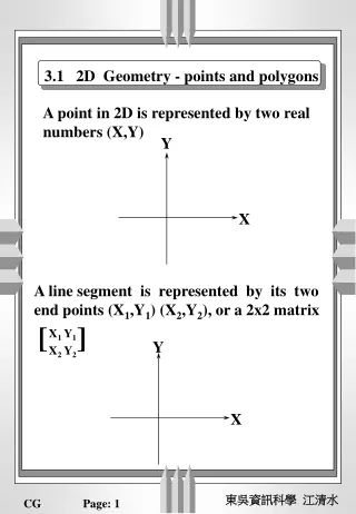
DEFORM Simulation Results 2D Hot Forging and Air Cool of Gear Tooth Geometry. Holly Quinn 12/04/2010. 2D Axisymmetric Model Workpiece (Yellow) is Plastic and 2200 °F Top and Bottom Dies are Rigid. All pieces are 300 °F. Workpiece will be re-meshed when interference exceeds 0.00099.

E N D
DEFORM Simulation Results2D Hot Forging and Air Cool of Gear Tooth Geometry Holly Quinn 12/04/2010
2D Axisymmetric Model Workpiece (Yellow) is Plastic and 2200°F Top and Bottom Dies are Rigid. All pieces are 300°F. Workpiece will be re-meshed when interference exceeds 0.00099. Initial Contact Pairs: 1. WP to Bottom Die WP to Top Die Top Die Workpiece Bottom Die DEFORM Model
Main Axisymmetric Geometry Modes Deformation Heat Transfer Step Settings Starting Step = -1 Number of Steps = 100 1 Step = 0.01” Die Displacement Max Strain in WP/step = 0.1 Primary Die = Top Die Iteration Settings Solver = Skyline Iteration Method = Newton-Raphson Convergence Errors 0.001 for Velocity 0.01 for Force Forging Simulation Settings • Process Conditions • Heat Transfer • Environment Temperature = 68F • Convection Coefficient=5.787e-6 But/sec/in2F • Diffusion • Environment Atom Content = 1.69% atm • Reaction rate coefficient = 1e-5 in/sec • Advanced • Contact Error Difference Tolerations = 0.0009
Materials Top Die Workpiece Bottom Die
Flash Flash Displacement
Two Areas examined: Points within gear “core” Points 6, 18, 21 Points near exterior of gear tooth Points 14, 15, 16 Grain Orientation Plot Average Grain Size from beginning to end of forging (Step 1 – 43) Microstructure Post Processing of Forging
Discrete Lattice: Cellular Automata, (50x50) Square Horizontal and Vertical BCs: Periodic, Wrap Around Grain boundary and Neighborhood: Grain Boundaries coupled to material flow: No Neighbor Hood: Moore’s Neighborhood, R=1 Dislocation Density Calculation Constants ε0=1 Q=416,780 h0=0.00075 r0=2000 K=6000 m=0.0055 Recrystallization Phenomena: DRX Nucleation Conditions for new grains: Function of a threshold dislocation density Nucleation Conditions for new grains: n/a Grain growth phenomena selection and material constants: Grain Growth: Function of GB migration velocity, constant=1 Flow Stress phenomena selection and material constants: n/a ρi = 1 D=0.1 δ=0.1 Initial MS Input: Generate GB and orientations separately: System generate, average GS = 0 Generate GB Orientations: System generate, random Initial dislocation density ρi=0.01 Microstructure Post Processing Settings
P21 P18 P6 Microstructure – Core Locations Grain Orientation,Step 1
P21 P18 P6 Microstructure – Core Locations Grain Orientation,Step 43
P21 P18 P6 Microstructure – Core Locations Grain Size Histogram,Step 1 Point 6: Average GS=9.70 Point 18: Average GS=9.50 Point 21: Average GS=9.76
Microstructure – Core Locations Grain Size Histogram,Step 43 Point 6: Average GS=2.05 Point 18: Average GS=1.89 P21 P18 P6 Point 21: Average GS=2.02
P21 P18 P6 Microstructure – Core Locations Grain Boundary Misorientation,Step 1
P21 P18 P6 Microstructure – Core Locations Grain Boundary Misorientation,Step 43
P14 P16 P15 Microstructure – Tooth Locations Grain Orientation,Step 1
P14 P16 P15 Microstructure – Tooth Locations Grain Orientation,Step 43
Microstructure – Tooth Locations Grain Size Histogram,Step 1 Point 14: Average GS=9.80 Point 15: Average GS=9.59 P14 P16 P15 Point 16: Average GS=9.81
Microstructure – Tooth Locations Grain Size Histogram,Step 43 Point 14: Average GS=1.97 Point 15: Average GS=2.07 P14 P16 P15 Point 16: Average GS=1.91
Gear Core Grain Size Changes Point 6: 9.70 2.05 Point 18: 9.50 1.89 Point 21: 9.76 2.02 Gear Tooth Grain Size Changes Point 14: 9.80 1.97 Point 15: 9.59 2.07 Point 16: 9.81 1.91 Decreased Grain Size in Core and Tooth Areas (from Step 1 to 43)
Main Axisymmetric Geometry Modes Deformation Phase Transformation Mesh #Structured Surface Mesh Layers=2 Layer Thicknesses: 1=.005, 2=.01 Workpiece Initialization Don’t Initialize Temperature Phase Volume Fraction (Austenite)=1 Temperature = 2200°F Step Settings Starting Step = -44 (last step of forging) (Max) Number of Steps = 1000 1 Step = 5°F Min Temp Time Step = 5 sec Max Temp Time Step = 30 sec Duration = 5400 sec Air Cool Simulation Settings Pyrowear 53 • Process Conditions • Heat Transfer • Environment Temperature = 68F • Coefficient=5.787e-06But/sec/in2F • Boundary Conditions • Outside of Gear, all surfaces • Media Type = Air • Environment Temperature = 68°F • Convection Coefficient = 5.787e-06 But/sec/in2F • Symmetrical planes in vertical and horizontal directions • Material • Pyrowear, Heat Treat *Heat Treat Wizard used for Model Setup
Pyrowear 53 Temperature (°F) Time Step #5 Time = 25 seconds Step #250 Time = ½ hour Step #425 Time = 1 ½ hrs
~1260°F Step #155 Time = 13 minutes Pyrowear 53 Temperature (°F)
Pyrowear 53 Phase TransformationTime=1000 seconds Temperature Tempered Ferrite + Cementite Austenite Martensite
Pyrowear 53 Phase TransformationTime=1800 seconds Temperature Austenite Tempered Ferrite + Cementite Martensite
Tempered Martensite Tempered Ferrite + Cementite Ferrite Martensite Pyrowear 53 Phase TransformationTime=5400 seconds Temperature