Download
1 / 32
340 likes | 494 Vues
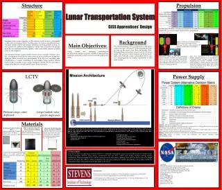
Lunar Exploration Transportation System (LETS). Baseline Design Presentation 1/31/08. Agenda. Current CDD Summary Team Disciplines Technical Description of Baseline Design Assessment of Baseline Design using CDD Recommended Changes to the CDD Statement of Work (SOW) Summary.

E N D
Lunar Exploration Transportation System (LETS) Baseline Design Presentation 1/31/08
Agenda • Current CDD Summary • Team Disciplines • Technical Description of Baseline Design • Assessment of Baseline Design using CDD • Recommended Changes to the CDD • Statement of Work (SOW) Summary
Team Disciplines • CDD Team • Eddie Kiessling • Technical Assessment Team • Nick Case and Matthew Isbell • Partnering Universities Team (SOW) • Seth Farrington
CDD Summary • Level 1 Requirements • Figures of Merit • Surface Objectives • Concept Design Constraints
Level 1 Requirements Landed Mass TBD 1st mission landing site is polar region Design must be capable of landing at other lunar locations Minimize cost across design Launch Date NLT September 30th 2012 Mobility is required to meet objectives Survivability ≥ 1 year Lander/Rover must survive conops. The mission shall be capable of meeting both SMD and ESMD objectives. The lander must land to a precision of ± 100m 3 sigma of the predicted location. The lander must be capable of landing at a slope of 12 degrees (slope between highest elevated leg of landing gear and lowest elevated leg) The lander shall be designed for g-loads during lunar landing not to exceed the worst case design loads for any other phase of the mission (launch to terminal descent).
Proposed FOMs • Surface exploration • Maximized Payload Mass (% of total mass) • Objectives Validation: Ratio of SMD to ESMD: 2 to 1. • Conops: Efficiency of getting data in stakeholders hands vs. capability of mission. • Mass of Power System: % of total mass. • Ratio of off-the-shelf to new Development • Minimize cost
Surface Objectives • Single site goals: • Geologic context • Determine lighting conditions every 2 hours over the course of one year • Determine micrometeorite flux • Assess electrostatic dust levitation and its correlation with lighting conditions • Mobility goals: • Independent measurement of 15 samples in permanent dark and 5 samples in lighted terrain • Each sampling site must be separated by at least 500 m from every other site • Minimum: determine the composition, geotechnical properties and volatile content of the regolith • Value added: collect geologic context information for all or selected sites • Value added: determine the vertical variation in volatile content at one or more sites • Assume each sample site takes 1 earth day to acquire minimal data and generates 300 MB of data • Instrument package baselines: • Minimal volatile composition and geotechnical properties package, suitable for a penetrometer, surface-only, or down-bore package: 3 kg • Enhanced volatile species and elemental composition (e.g. GC-MS): add 5 kg • Enhanced geologic characterization (multispectral imager + remote sensing instrument such as Mini-TES or Raman): add 5 kg
Concept Design Constraints • Surviving Launch • EELV Interface (Atlas 401) • Mass • Volume • Power • Communications • Environments • Guaranteed launch window • Survive Cruise • Survive Environment • Radiation • Thermal • Micrometeoroids
Concept Design Constraints • Lunar Environment (@ poles and equator) • Radiation • Micrometeoroid • Temperature • Dust • Lighting • Maximize use of OTS Technology (TRL 9) • Mission duration of 1 year • Surface Objectives Reference: Dr. Cohen
Mars Viking Lander • First robotic lander to conduct scientific research on another planet • Dry Mass 576 kg • Science 91kg • Dimensions 3x2x2m • Power: • 2 RTG • 4 NiCd • Survivability: -V1:6yrs 3mo -V2:3yrs 7mo
Baseline Assessment • Structures • Thermal Systems • Payload and Communications • Power Systems • GN&C • Concept of Operations
Structures • EELV Interface • Titan III which delivered the Viking lander is comparable to the Atlas V-401 • The lander shall be designed for g-loads during lunar landing not to exceed the worst case design loads for any other phase of the mission (launch to terminal descent). • Mars Viking Lander experienced no more than 4 g during launch • LETS will experience no more than 5.5 g during launch • The lander must be capable of landing at a slope of 12 degrees (slope between highest elevated leg of landing gear and lowest elevated leg) • Mars Viking used bonded aluminum honeycomb crush pads • LETS could use similar technologies
Structures • Lunar Environment (Radiation, Micrometeoroid, Temperature, Dust) • Thermal cycles vary greatly • Viking thermal fluctuation was approx. ΔT=160 K • LETS can expect a thermal fluctuation approx. ΔT=273 K • εT = α*ΔT • σT = -E* α*ΔT • Resistance to dust abrasion • Viking used a silicon paint to protect the surfaces from Martian dust • LETS could use a similar product • Landed Mass (TBD) • Viking required a bio-shield and a aero-decelerator • LETS will not require these items • Viking structural frame used lightweight aluminum and bonded aluminum honeycomb crush pads • LETS could use similar technologies and also benefit from major advancements in materials
Thermal Systems • Viking Thermal System • Passive • Geometry • Internal thermally controlled compartment • Structurally integrated thermal sinks • Increased or Decreased Surface Area where applicable • Thermal Coatings • Proper infrared emittance • Proper solar absorbance • Thermal Compartment • Critical equipment will be housed in compartment • Temperature will be dependent upon operating temperatures of critical equipment • Insulation • Thermal control between equipment and environment • Radiation shield • Active • Heaters • Continuous operation • Thermostatically controlled • Redundant systems
Thermal Systems • LETS Thermal System • Different Thermal Cycles • Mars Temp. Range:148K to 298K • Lunar Temp. Range: 50K to 373K • Difference in more than 100°Ctotal fluctuation • Heaters and Insulation changes to accommodate different thermal cycles • Statically charged lunar dust changes the absorptance, α of the spacecraft surfaces • Use of polarized surfaces/coatings to reduce lunar dust accumulation
Payload and Mobility • Scientific Options • Measure 15 samples in the dark and 5 samples in light. • The Viking Lander did not move, but it used an SSRA with a boom, collector head, and shroud unit, capable of collecting a variety of material elements. • Each sampling site separated by 500 m. • The Viking Lander did not have this capability. • Determine composition, geotechnical properties, and volatile content of regolith. • The Viking Lander used an X-ray Fluorescent Spectrometer (XRFS) to perform a chemical analysis. • Enhanced geological characterization (multi-spectral imager & remote sensing instrument). • The XRFS plus a remote sensing instrument may be used for this function.
Observation • Camera Options • Viking Lander camera system • Looked at surface and was able to measure optical density of the atmosphere • Geologically characterize the surface • Look for macroscopic evidence of life • LETS camera system • Observe electrostatic dust on the horizon • Study change in lighting conditions and the effects of surrounding environment • Aid in Earth observation and control of data collection
Communication • Transmission options • Direct transmission used by Viking • Relay from Viking Orbiter to Earth • UHF linked used to transmit data at speeds of 4000 and 16000bps • Transmission Criteria for LETS • => 1 Earth day to transmit data • Transmission Path Options • Direct transmission from the Moon to Earth • Storage of data until DLS is obtained • LRO (Assume) to relay data to Earth
GN&C • The lander must land to a precision of ± 100m 3 sigma of the predicted location. • Viking: Orbiter/Lander separation until the Lander was on the Martian surface • The propulsion system along with a navigation system consisting of radars, gyros, accelerometers, etc to guide the Lander through Mars atmosphere and a soft accurate landing on the Martian surface. • GN&C was not responsible for any operations after landing • LETS: Operations will commence upon landing, and will continue for the duration of the mission. • The lander must be capable of landing at a slope of 12 degrees • GN&C in conjunction with structure will ensure that the Lander can function on a 12 degree slope. • Mobility is required to meet objectives • GN&C will be responsible for rover and SRV deployment.
Power Systems • Operational Period • Viking Mars Lander was 90 days • LETS will be 365 days • Power Required Systems • Viking Lander • Telemetry • Communication • Thermal systems • Instrumentation • Ascent and descent operations • Caution and warning systems • Power conditioning • Regulate power • Power storage • LETS will be required to supply power to similar systems
Power Systems • Power Supply Options • Solar Cell • Battery • RTG
Power Systems • Radioisotope Thermoelectric Generator (RTG) • Nuclear Yield: • Fuel: Plutonium – 238 • Nominal Heat Generation Rate: • 682 Watts • Weight & Dimensions: • 15.4 Kg (34 lbm) • 53 cm x 41 cm (23 in x 16 in) • Power Output: • 35 to 780 Watts
Advantages ASRG/SRG (Nuclear) Constant Power Supply Thermal Output can be utilized for thermal systems Requires Fewer Batteries Solar Panels Minimize Cost High Power to Weight Ratio Clean Energy Politically Safe Disadvantages ASRG/SRG (Nuclear) Political Affairs Nuclear Waste Hazardous / Contamination Expensive Solar Panels Degrade Over Time Non-constant Power Supply No Thermal Output Susceptible to Lunar Environmental Conditions Requires Many Batteries Power Systems
SOW Committee • Statement of Work for Partners • Software • Communications
Statement of Work • ESTACA • Sample Return Vehicle • Southern University (SU) • Mobility Concepts
SOW Committee • Software Protocols • Computer Aided Design (CAD) • Unigraphics NX as standard for UAH and Southern University • CATIA as standard for ESTACA • CAD Translation Options • TransMagic • MathdataHQ.com • Professional Documents • MS Office • Text Documents – MS Word • Spread Sheets – MS Excel • Slide Presentation – MS Power Point
SOW Committee • Communication Protocols • Meetings • One meeting per week required • Minutes will be required • UAH and ESTACA • Teleconference, or a web-based video chat • UAH and Southern University • Video conference, teleconference, or web-based video chat Note: Minute template will be provided • File Sharing Protocols • WebCT – Primary • Basic Email - Secondary
CDD Recommendations • Is the true design after we land?