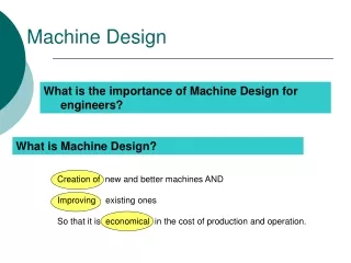
Understanding Static Loading in Machine Design: Failures and Principal Stresses
In this lecture on machine design, we explore the critical design considerations for components under static loading conditions. Key topics include various failure modes such as yielding, fracture, buckling, fatigue, and creep. The discussion will delve into the concepts of principal stresses and the use of Mohr's Circle for stress analysis. Understanding these aspects is crucial for ensuring that machine components can withstand external forces without failure. Suitable for students in mechanical engineering technology, this lecture provides a fundamental overview of static load considerations in design.

Understanding Static Loading in Machine Design: Failures and Principal Stresses
E N D
Presentation Transcript
MT-253 MACHINE DESIGN Lecture #5 Syed EhtishamGillani Lecturer Department of Mechanical Engineering Technology University of Technology Nowshera
Design for Static Loading This section of machine design deals with the design considerations against static loading, It will include: • Overview of different modes or types of failures. • Concept of principal stresses and Mohr Circle • Theories of Failure.
Modes of Failure • A machine component fail when the stresses induced by external forces exceed the maximum strength of that component. • Failure in a machine component can occur in various ways: • Yielding • Fracture • Buckling • Fatigue • Creep
Modes of Failure Yielding • When a component/material undergoes excessive load such that it start deforming plastically (permanent deformation) and become unable to perform its function, such a failure is called yielding. • This mostly occurs in ductile materials. • Yield strength or yield stress is the material property defined as the stress at which a material begins to deform permanently.
Modes of Failure Fracture • When a component/material undergoes excessive load such that it suddenly tears apart and failure occurs, such a failure is called Fracture. • It occurs in brittle materials and commonly called brittle fracture. • Yielding is also ductile fracture.
Modes of Failure Buckling • When a thin column/beam/structural member is subjected to an excessive axial compressive load, a sudden sideways (perpendicular to the axis) deflection occurs in it, this is called buckling. • Once buckling occurs, there are majority of the chances that the structure will collapse.
Modes of Failure Fatigue • Fatigue is a common type of failure in which structures/components fail when they are subjected to a cyclic or fluctuating loads. • Fatigue failure normally occurs quite below the maximum strength of that material. • Fatigue failure occurs in three stages: • When cyclic load occurs, the damage develops on the microscopic level and grows until a macroscopic crack is formed. • The macroscopic crack grows for each cycle until it reaches a critical stage. • The cracked component breaks because it can no longer sustain the load.
Modes of Failure Creep • When a component undergoes a constant load at high temperature for a period of time, creep failure occurs. • Creep also occurs at room temperature with constant load, but it will take much longer to fail in such condition. • Creep failure also occurs in three stages: • Primary Creep: it starts at a rapid rate and slows with time. • Secondary Creep: it has a relatively uniform rate. • Tertiary Creep: it has an accelerated creep rate and terminates when the material breaks or ruptures.
Mohr’s Circle and Principal Stresses • When a mechanical component undergoes a combination of forces (tensile, compressive and shear forces) it give rise to compound stresses. • In compound stresses, the resultant stress at a point consists resultant of normal and shear stress. • In such situations, principal stresses are used to represent the state of stress at a point. • Principal stresses are the maximum normal stresses a body can have at a point.
Mohr’s Circle and Principal Stresses • The object in reality has to be rotated at an angle θp(Principal angle) to experience no shear stress. • In order to find these principal stresses and Principal angle at a point, a graphical method is used known as Mohr’s circle. • Mohr's circle also gives the value of maximum shear stress and its orientation (angle θs).
Mohr’s Circle and Principal Stresses • It is named Mohr’s circle because Christian Otto Mohr was its developer. • It is a graphical method used for the evaluation of principal stresses, principal angles and maximum shear stresses for a given element of component under compound stresses. • The concept of Mohr’s circle can be explained with the help of following example.
Mohr’s Circle and Principal Stresses • Consider a rod with a circular cross-section and look at a square element at the surface of the rod: • If the rod is subjected to a tensile and compressive force at its both ends, as shown below:
Mohr’s Circle and Principal Stresses • And then the rod is subjected to a torque (twisting force) at its both ends:
Mohr’s Circle and Principal Stresses • The square element will experience the following stresses: • Consider two points A and B on the two faces of the element
Mohr’s Circle and Principal Stresses See class notes for further derivation of Mohr’s circle!
Mohr’s Circle and Principal Stresses Fig. 1 Fig. 2
Mohr’s Circle and Principal Stresses Center C of Mohr’s circle is given by: Radius R can be calculated using Pythagoras theorem Principal angle θ can be calculated as (divide by 2 to get value of θ) Finally Principal Stresses can be given as:
Mohr’s Circle and Principal Stresses Problem: Draw the Mohr’s Circle of the stress element shown below. Determine the principle stresses and the and the principal angle of orientation.What we know:σx= -80 MPaσy= +50 MPaτxy= 25 MPa
Maximum Shear Stress and its orientation • τmax = R • τmin = -R 2θs = 2θp + 90
Maximum Shear Stress and its orientation Problem: Using Mohr's circle, Find the following: Principal normal stresses (σ1 and σ2) ; The principal direction (θp); Maximum shear stress (τmax); Maximum shear direction (θs)
Assignment #2 Q:1: Draw the Mohr’s Circle of the stress element shown below. Find the Principal stresses, Principal orientation, Maximum shear stress and shear orientation. Q:2 Draw the Mohr’s Circle of the stress element shown below. Find the Principal stresses, Principal orientation, Maximum shear stress and shear orientation. Note: Quiz #2 will be held on 29th Oct 2018