Download
1 / 29
290 likes | 502 Vues
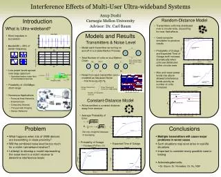
Interference Effects of Multi-User Ultra-wideband Systems. Anup Doshi Carnegie Mellon University July 31, 2003. Outline. Intro Models Observations Summary. What is an Ultra-wideband Signal?. Short impulses in succession FCC Definition – Bandwidth > 25% of center frequency.

E N D
Interference Effects of Multi-User Ultra-wideband Systems Anup Doshi Carnegie Mellon University July 31, 2003
Outline • Intro • Models • Observations • Summary
What is an Ultra-wideband Signal? • Short impulses in succession • FCC Definition – • Bandwidth > 25% of center frequency
GPS PCS 802.11a “Part 15 Limit” -41 dBm/Mhz UWB Spectrum 1.6 1.9 3.1 5 10.6 Frequency (Ghz) Source: Intel Advantages of UWB • Low power levels spread over large spectrum • Operates below noise floor of narrowband devices • Possibility of >500Mbps short range
UWB UWB UWB LAN/WLAN UWB UWB Broadband Potential Applications are Numerous • Personal Area Network • Interconnect Computers, Devices, PDAs, Printers • Entertainment...TV, Camcorder, DVD • Music…MP3, Audio Systems, etc • Safety • Through-wall Imaging • Sensor Network • Lots of other exciting applications Image Sources: Intel, AetherWire
Why Only Now? • Started as impulse radar, 1960’s • Primitive forms, simple communication • Studied & used by military • New technology enables digital comm., 1990’s • Commercial applications seen by several companies • 1998 - Petitioned FCC to review potential uses • 2003 - FCC approves development of conservative applications
Problem… • What happens when lots of UWB devices are transmitting in close proximity? • Will the combined noise level be too much for a victim narrowband receiver? • Existing studies claim minimal effects • Done by various agencies and companies • Those studies do not examine all cases… This is my job!
Constant-Distance Distribution Multiple UWB devices located three meters from a victim VICTIM
Characterizing the Transmitters • Units turn on and off in a 2-state Markov Process • Switching times are Exponential Random Variables • Time until on ~ Exponential(λ) => mean 1/λ sec • Time until off ~ Exponential(µ) => mean 1/µ sec • Rho=ρ= λ/µ λ Unit Off Unit On µ
Characterizing the Transmitters • Total Number on modeled as a Markov Chain • Steady-state probabilities: (N-1)λ … λ Nλ 0 1 2 N-1 N … µ 2µ Nµ
How Does the System Act Over Time? λ =1, µ=2
How Does the System Act Over Time? λ =1, µ=2 Total Number of Units On
Noise Level in Victim Receiver • Each UWB signal modeled as White Noise • Total Noise= N0+M(t)*N1 Ambient Noise Floor (=kTw) Power Received at Victim from UWB Signal Number of Transmitters On (Markov Chain)
Some Properties of This Model • Autocorrelation Spectral Density
Probability of Error in Receiver • On Average: (µ=1)
Other Ways to Describe Model • Probability of Outage • P(outage)=Probability( Perr > Pe* ) • Pe*=.1, .01 • Perr= • Expected Time of Outage • E(T10) = T1+aN,1E(T20) • E(T20)=T2+aN,2E(T10)+bN,2E(T30) • … • E(TN0)=TN+E(T(N-1)0)
P(outage), Expected Time of Outage (µ=10) (µ=1)
Random-Distance Distribution UWB devices distributed uniformly in a circular area around victim VICTIM
Properties of Random-Distance Model • Moved to a computer simulation • Experimentally calculated: • P(outage), • Expected Time of Outage, • Max and mean power levels over time • Done on Matlab – Monte Carlo simulation
P(outage) & Expected Time of Outage (µ=1) (µ=10)
Broadband Observations • Multiple transmitters will cause major problems in worst cases • Such situations may soon arise in real-life situations • Important to consider every possible case in testing
Future Work • Need to consider many more variables • Receiver type • Frequency, PRR • Different distributions • Once 802 Standard comes out, incorporate into model • Possibly Multi-Band OFDM (TI, Intel) • Possibly Dual-Band (Time Domain, Motorola)
Summary • Characterized an aggregate of UWB transmitters • Realized various methods of measuring effect on victim receiver • Concluded that as number of UWB transmitters increase, performance of victim receiver attenuates
Acknowledgments • Prof Baum • Prof Noneaker, Prof Xu • ECE Faculty and Grads • NSF