Download
1 / 14
190 likes | 585 Vues
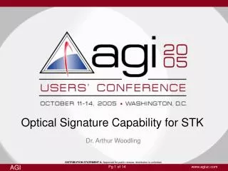
Optical Signature Capability for STK. Dr. Arthur Woodling. DISTRIBUTION STATEMENT A. Approved for public release; distribution is unlimited.

E N D
Optical Signature Capability for STK Dr. Arthur Woodling DISTRIBUTION STATEMENT A. Approved for public release; distribution is unlimited.
OPTISIG Inquires To:Dr. Arthur Woodling / MS 118Teledyne Solutions, Inc.5000 Bradford DriveSuite 200Huntsville, Al 35805(256) 726-6710Arthur.Woodling@tdytsi.com OPTISIG/STK Interface Inquires To:Jeffery King / MS 118Teledyne Solutions, Inc.5000 Bradford DriveSuite 200Huntsville, Al 35805(256) 726-2597Jeffery.King@tdytsi.com Acknowledgements And Contacts • OPTISIG has been developed under the technical direction of the T&E Directorate/Data Analysis Division, U. S. Army Space and Missile Defense Command, Huntsville, Alabama • The OPTISIG/STK interface software development was funded by Teledyne Corporate Independent Research and Development
Scenario Target Libraries STK trajectory STK plots R,V q, f, y OPTISIG STK Connect Linkages Outline • OPTISIG Overview • OPTISIG Heritage And Users • The Physics of OPTISIG • OPTISIG/STK Interface • Simple Mission Planning Exercise • Summary
OPTISIG Structure Primary Applications Standardized Target Capability Target Type Fidelity Approximate Run Time Fortran Subroutine ~30,000 Lines Multi-Target Threat Complex Generation, System Simulations, Discrimination Algorithm Development, Acquisition and Track Studies Target Model Libraries Distributed With OPTISIG Axisymmetric Target Shapes Described by Cones, Cylinders, Spheres, Disks, Plates High to Medium 1 Sec Per Target OPTISIG Overview • OPTISIG provides optical signatures for missile systems and payloads between Visible and Long Wave Infrared • Models targets from ascent through reentry • Results verified to the Industry standard OSC code for typical target classes (RVs, replicas, balloons)
OPTISIG Heritage And Users OSC Developed 1972 GSTS AST Detailed Validated Code For Simulating Optical Signatures of BMD Systems XoDiS FASTSIG Developed 1985 High-Speed Single Target Optical Signature Generation OPTISIG Subroutine Developed 1991 NTB High-Speed Multi-Target Optical Signature Generator Using Pregenerated Model Libraries SBIRS STB SSGM ISTC GBI/EKV
Time varying: • Projected Area • Thermal Emission • Reflected Sun, Earth, Albedo Sun Optical Properties, a, e, r(l) Sensor Aspect Angle Precession About Angular Momentum Axis Precession ½ Angle Solar Flux Angular Momentum to CG Spin Rate Material Layering and Thermophysical Properties, d, cp, k Cloud Albedo Emitted Earthshine Earth Albedo The Physics Of OPTISIG • Target Models • Shape Primitives • Thermal Properties • Optical Properties • Natural Sources • Solar • Earthshine • Earth Albedo • Aerothermal • Target Motion • Rigid Body Dynamics (Precession)
OPTISIG/STK Interface • Windows application • Can use the power of STK’s flight and constraint algorithms • Provides Radiant Intensities using an industry recognized tool (OPTISIG) • Uses STK Connect linkages • Can be utilized for mission planning and battle management exercises
Simple Mission Planning Exercise • MSX Satellite (Sensor Platform) • Three Infrared detectors (hypothetical) • Short Wave IR • Medium Wave IR • Long Wave IR • Data Rate: 0.5 Hz • Noise Level: 1e-18 W/cm2 (each band) • DMSP_5D-1-F06 Satellite (Target) • Schedule mission for June 1, 2004 • Require at least 200 seconds of target viewing with a signal-to-noise ratio of at least 8.0 Disclaimer: All sensor parameters used in this exercise are fictitious, any resemblance to real sensors, living or dead, is purely coincidental.
Target at first access Sensor at first access STK Predicts Multiple Accesses • Sensor views target on ten separate occasions on 6/1/2004
Access Start Time (UTCG) Stop Time (UTCG) Duration (sec) ------ ----------------------- ----------------------- ----------------- 1 1 Jun 2004 00:16:51.404 1 Jun 2004 00:22:32.702 341.298 2 1 Jun 2004 01:07:59.307 1 Jun 2004 01:13:20.481 321.174 3 1 Jun 2004 01:59:22.814 1 Jun 2004 02:04:08.682 285.868 4 1 Jun 2004 02:50:32.394 1 Jun 2004 02:54:55.024 262.629 5 1 Jun 2004 03:41:57.888 1 Jun 2004 03:45:40.609 222.721 6 1 Jun 2004 04:33:09.218 1 Jun 2004 04:36:25.193 195.976 7 1 Jun 2004 05:24:36.993 1 Jun 2004 05:27:07.560 150.567 8 1 Jun 2004 06:15:50.282 1 Jun 2004 06:17:49.896 119.614 9 1 Jun 2004 07:07:20.947 1 Jun 2004 07:08:28.054 67.106 10 1 Jun 2004 07:58:36.658 1 Jun 2004 07:59:07.271 30.613 Global Statistics ----------------- Min Duration 10 1 Jun 2004 07:58:36.658 1 Jun 2004 07:59:07.271 30.613 Max Duration 1 1 Jun 2004 00:16:51.404 1 Jun 2004 00:22:32.702 341.298 Mean Duration 199.757 Total Duration 1997.567 STK Access Summary Report • First five accesses satisfy 200 second viewing duration criteria • Last five accesses are too short • Run OPTISIG to check first five accesses for sufficient signal on the focal plane
Set Up OPTISIG Run • Associate STK trajectories with OPTISIG sensors and targets • Set up sensor noise and data rate parameters • Set up OPTISIG environmental parameters
1 Jun 2004 00:16:51.404 1 Jun 2004 00:22:32.702 Long IR Medium IR Reflected Radiation Short IR OPTISIG Results (Access Interval 1) • Access interval 1 • Yields data above 8.0 SNR threshold • Not sufficient for 200 second duration • Short IR band shows off OPTISIG’s ability to model reflected radiation from Sun & Earth • Access intervals 2, 3, and 4 show similar threshold deficiencies
1 Jun 2004 03:41:57.888 1 Jun 2004 03:45:40.609 Long IR Medium IR Short IR OPTISIG Results (Access Interval 5) • Access interval 5 • Each sensor band yields data above required threshold for the entire interval • Only access meeting or exceeding mission requirements
Scenario Target Libraries STK trajectory STK plots R,V q, f, y OPTISIG STK Connect Linkages Summary • OPTISIG/STK is a Windows driven application • Allows the user to utilize the power of STK’s flight and constraint analysis algorithms • Provides optical radiant intensities via the use of an industry recognized prediction tool (OPTISIG) • Interface is established via STK Connect linkages • Can be utilized for mission planning and battle management exercises