Download
1 / 16
160 likes | 323 Vues
Investigation of Combustion Instabilities in Low NO x Gas Turbines*. Tim Lieuwen and Ben T. Zinn Schools of Mechanical and Aerospace Engineering Georgia Institute of Technology Atlanta, GA 30332 AIAA 36th Aerospace Sciences Meeting January 1998 Reno, Nevada

E N D
Investigation of Combustion Instabilities in Low NOx Gas Turbines* Tim Lieuwen and Ben T. Zinn Schools of Mechanical and Aerospace Engineering Georgia Institute of Technology Atlanta, GA 30332 AIAA 36th Aerospace Sciences Meeting January 1998 Reno, Nevada ____________________________________________________________________ * Research supported by AGTSR under contract #95-01-SR031; Dr. Daniel B. Fant, contract monitor
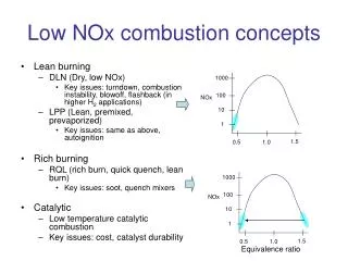
To reduce NOx emissions, gas turbines are being designed to operate in a lean, premixed mode of combustion However, these lean premixed combustion systems often develop longitudinal combustion instabilities, limiting the range where they may be operated The objective of this study is to develop an understanding of the mechanisms responsible for these instabilities to aid in development of methods to eliminate them Combustion Instabilities in Low NOx Gas Turbines
Experimental data indicates that the chemical time increases more and more rapidly as the equivalence ratio (f) decreases. Dependence of Heat Release Rate on Equivalence Ratio Zukoski's Experimental Data
To quantitatively examine this effect, an unsteady WSR model was developed, and subjected to perturbations in the inlet f. Results show that the response of the unsteady rate of reaction increased as much as 200 times as f was decreased from stoichiometric to lean mixtures Conclusion: These results indicate that f oscillations (i.e., unmixedness) induce strong heat release oscillations that can drive combustion instabilities under lean conditions Results of a well-stirred reactor (WSR) model
A Mechanism for Combustion Instabilities due to Unmixedness Flame Region Heat Release Oscillations AcousticOscillationsin Inlet andFuel Lines Equivalence Ratio Fluctuations
Time evolution of disturbances responsible for the onset of instability
Time evolution of disturbances responsible for the onset of instability (continued) • From Rayleigh's Criterion an instability can occur if t1 + tconvect + tchem=(n-1/2)T • However: • If distance from injector to flame region is much shorter than a wavelength: • t1/T<<1 • For low frequency instabilities: • tchem/T<<1 • Thus, an approximate instability condition is: • tconvect /T=n - 1/2 • Conclusion: tconvect /T is a key parameter in combustor stability
Combustor Model • A model was developed to predict the linear stability limits of the observed longitudinal combustion instabilities based on this mechanism
Model Results - Influence of Convective Time Delay on Combustor Stability Parameter Ranges: = 40, 60, 80 m/s Laf = 0-0.15 m f =0.6-1 • Model Results are in good agreement with experimental data from DOE - FETC • However, model overpredicts instability growth rates and instability regions Choked fuel injector, p’=0 B.C. at inlet
Combustor Model • Linear Acoustics Model • 1-D Wave solutions in fuel line and Regions i and iii: • Boundary Conditions: • Combustor Exit: compact choked nozzle • Upstream end of inlet duct: p'=0 • Upstream end of fuel line: v'=0 • Matching Conditions: • Flow through fuel orifice: mf = Kor(DP)1/2 • Acoustic Oscillation in Regions i and iii matched by integrating across the flame region which was assumed to be acoustically compact e.g. without mean flow or area discontinuities: • Solution determines the complex frequency w=wr+iwi
Combustor Model (continued) • Heat Release Model: • Combustion process assumed to behave as a well stirred reactor (WSR) • Assuming a quasi-steady behavior (i.e. tchem <<T) the following expression for the linearized response of a WSR to inlet flow perturbations can be derived: Q' = z1m' +z2p' + z3f' • For the results presented here, heat release perturbations only due to fluctuating f • Unmixedness Model: • f perturbation at fuel injector: • Mixture assumed to convect with the mean flow with unchanged composition: f'(x,t) = finj'exp(iw(t-x/u))
Combustion Process Response Model Using a global kinetic mechanism for propane and a WSR residence time of .1 ms.
Fuel Line- Orifice Dynamics Orifice Pressure drop = 2 atm., Combustor Pressure =10 atm., Fuel line Mach # = .05
Model Results- Effect of Fuel Injector Location on Combustor Stability Mean flow velocity = 40 m/s 80 m/s tconvect/T3/2 tconvect/T1/2 tconvect/T1/2 Stable Unstable
Model Results- Effect of Fuel Line Dynamics on Combustor Stability Mean flow velocity Lfuel/l1/2 Lfuel/l1 = 40 m/s Laf = 0.08 m Stable Unstable • Combustor stability altered when unstable wavelength matches the fuel line length• This suggests a variable length fuel line as a passive control approach
Summary and Conclusions • Under lean conditions, unmixedness can cause large heat release rate oscillations • tconvect/T is a key parameter in describing combustor stability • Model predictions are in agreement with experimental data • Combustion instabilities could be suppressed by: • Enhancing mixing in the inlet duct • A judicious location of the fuel injector • A variable length fuel line