Download

1 / 11
110 likes | 218 Vues
The kV2 Totalization feature allows the integration of data from up to five meters, including four external pulse inputs, offering extensive configuration options for monitoring and controlling various metrics. With support for external pulse scaling and a variety of output configurations, users can create custom totalization channels to combine and manage data effectively. This feature enhances functionality while providing real-time insights through alerts and diagnostics. Ensure compatibility by using the Multiple I/O option board for optimal performance.

E N D
Totalizing with the kV2 Revised 6-7-00
Z Soft Switch • Totalization and External Pulse Input Scaling • Enables combining data from up to 5 meters • 4 external meter inputs plus the kV2 metered data • External inputs require use of the Multiple I/O option board • Up to 8 data combinations allowed -- “totalization maps” • Add or subtract inputs with the same engineering units • May use one totalization channel as input to a second totalization channel • Enables data scaling of external pulse inputs • External inputs may be recorded and displayed as unscaled raw pulse counts without the Z soft switch installed
Multiple I/O Option Board • Expanded Functionality • 2 Three-Wire Outputs • 6 Two-Wire Outputs • 4 Pulse Inputs (Three-Wire or Two-Wire) • 1 RTP Input • All outputs configurable for: • Pulse Initiator functions • Alerts, Diagnostics, & Cautions • Load Control Operation • Solid State relays • Max. ratings: 120 VAC, 0.1 AAC; 170 VDC, 0.1 ADC • RTP and pulse inputs require 5~24 VDC, 8 mADC minimum • Not compatible with the kV meter
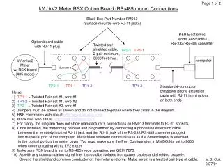
kV kV kV2 Wiring the external inputs • An external DC power supply must be connected in series with the “K” lines between between the kV2 inputs and the pulse initiator outputs • If only two-wire inputs are used, use the kV2 “K” and “Z” input leads • Shield signal lines and surge protect the power supply as needed • The kV2 inputs must see 5 VDC minimum to be recognized • Maximum input pulse rate = 30 pulses/second • Minimum input pulse duration = 33 milliseconds/pulse • Inputs are sampled 60 times per second • Every input state change is counted as a pulse K1 Z1 Source Meters (4 max.) Totalizing Meter Z2 K2 Power Supply 5~24V DC K1 & K2
kV2 MI/O Pulse Input Schematic User Connections Inputs to the Microprocessor User Connections Inputs to the Microprocessor Note: Four inputs are available. Only two are shown here for clarity. If only 2-wire inputs are used, connect to K & Z inputs.
kV2 MI/O Pulse FM C Output Schematic Outputs from the Microprocessor User Connections Outputs from the Microprocessor User Connections
kV2 MI/O Pulse 2-wire Output Schematic Outputs from the Microprocessor User Connections Note: Six two-wire outputs are available. Only two are shown here for clarity.
Application Considerations • Combine inputs with the same unit type (Wh + Wh, varh + varh, etc.) • Combining kVA (Phasor, Apparent) pulses results in an “arithmetic” total of vector quantities and may result in unexpected answers • Consider combining orthogonal quantities (wh, varh, distortion VAh), then convert them to a Phasor or Apparent kVAh value • External equalization of pulse inputs is not required • Pulse scaling is done via software programming
External Input Pulse Scaling • Scaling pulse inputs for programmed input: • Determine the primary value of the pulse inputs • Divide by the TF of the kV2 totalizing meter • Program the kV2 external pulse input parameter with the resulting value • Example: • Sub-meter #1 is programmed for a pulse output of 0.15 wh/pulse (secondary) with a CTR=600:5, TF=120. • A kV2 meter has a CTR=400:5, TF=80. • Determine the program value to correctly totalize the pulse input from Sub-meter #1 with the kV2 measured energy. • Solution: • Primary value of pulse input = 0.15 wh/pulse * 120 = 18 wh/pulse • Programming value = (18 wh/pulse) / 80 = 0.225 wh/pulse
Programming Considerations • Make sure the measurement Profile contains at least one Totalization entry and one External Pulse Input (scaled) • To display the external inputs individually as scaled values, create separate Totalization channels for each input, map each input to its own totalization channel, and display the totalized channel. • Make sure the Totalization option is enabled for the MeterMate Program file • Define the I/O and Alerts support table first • Define the Totalization support table second • Before programming the kV2 meter, make sure the Z soft switch is enabled and the Multiple I/O option board is installed • If you wish to record the pulse inputs and/or totalized result, make sure either the R or X soft switch is enabled and the Recorder support table is configured appropriately • Data accumulations may be selected for display, and will always appear in the Site Status report from MMDOS