Download
1 / 20
210 likes | 413 Vues
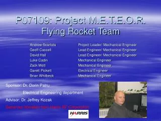
BYU Rocket Team 2009-2010. Special thanks to: Boise Discovery Teens Club Jeff Smith Dr. David Fullwood. Outline. About the Competition About the Rocket Nose Body Fins Flight Plan Electronics Deployments Simulations Motor Recovery Plan. The Competition.

E N D
BYU Rocket Team 2009-2010 Special thanks to: Boise Discovery Teens Club Jeff Smith Dr. David Fullwood
Outline • About the Competition • About the Rocket • Nose • Body • Fins • Flight Plan • Electronics • Deployments • Simulations • Motor • Recovery Plan
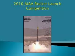
The Competition • Intercollegiate Rocket Engineering Competition (June 17, 2010) • Sponsored by ESRA • Goals: • Design, build, and launch a rocket to reach 10,000 feet AGL • Minimum 10-lb payload • Closest to 10,000 feet wins • Rocket must reach at least 5000 feet and not exceed 12,000 feet to receive points for altitude
Last Year • One successful Launch • Learned lots of basics • Most components were pre-fabricated
This Year • Still learning the basics • Manufacturing most components “in house” • Building off of last year’s design
Design Overview Nose Cone Body – 1: Payload Coupler 1: Nose Drogue Body – 2: Chute Storage Coupler 2: Altimeter Body – 3: Motor and Fins Coupler 3: Tail Drogue
Nose • Design • Ogive shape will provide the best aerodynamics for our anticipated velocity (760 ft/s) • Contour based on last year’s design • Manufacturing • Created a wood form on a lathe • Currently preparing form for pre-preg layup • Integration • Coupler 1 will be rigidly fixed to the cone • Nose cone chute will attach to the nose cone bulkhead
Body: Part 1 – Payload Bay • Body section will fit on to coupler 1 and be rigidly fixed to coupler 2 • Payload Requirements • Must weigh 10 pounds (competition rule) • Must be fit inside body tube (design team) • Payload Design • Modified RC aircraft (Firebird) • Deploy payload with main chute (~1,500 feet) • Remaining weight will be sand • Testing
Body: Part 2 – Chute Storage • Integration • Body section will fit on to coupler 2 and be rigidly fixed to coupler 3 • Main chute will attach to bulkhead 3 • Main chutes will be stored here • Manufacturing • Rolled carbon fiber 5 harness pre-preg • Cut to 46 inches
Body: Part 3 – Motor and Fins • Motor will be housed here • Manufacturing • Rolled carbon fiber 5 harness pre-preg • Cut to 46 inches • Integration • Tail Drogue will attach to bulk head 4 • Motor will mount inside body part 3 • Body part 3 will slip fit over coupler 3 • Slots will be cut for fins • Fins will attach to the bottom
Fins • Trapezoidal Design • Manufacturing • Aluminum plate (1/8”) • Will be water jet cut to desired dimensions • Integration • Tabs will fit into body tube slots • Fins will be anchored with epoxy and mechanical fasteners
Flight Plan - Overview • Launch • Deploy drogue chute before 10,000 feet (“zipperless” rear separation) • Apogee should be very close to 10,000 feet – then fall about 8,500 feet • Deploy main chute, nose cone and payload at 1,500 feet • Recover all parts within 2 hours
Flight Plan - Electronics • AIM USB Altimeter ($115) • 2 Deployments: • Main parachute • Drogue (apogee or user defined) • Two 9V batteries for redundancy • Our uses • Deploy brake system and drogues (drogue setting) • Deploy main parachute (main setting) • Purchased 2 for deployment redundancy
Flight Plan – Electronics (cont) • Electronics Bay will be inside coupler 3 • Pressure sensor holes will line up using a ‘belt’ of body tube material • Wires from altimeter attach to Davey Fire Electric Matches (low current). • Gunpowder inside Silly Pipe end cap ignites to pressurize body tube and eject recovery system.
Motor • Minimum launch height must be >10,000 feet • M-motor will work ($750) • Cessaroni L1115 will be used for test launch (7,000 ft AGL) • 4,908 N-sec Impulse (Full L) • Test Launch (May 22, 2010) • With Utah Rocket Club • Must be UNDER 10,000 ft • FAA waiver • NAR L2 Certification required
Recovery Plan • Rent a 4x4 and small trailer • Make sure we have at least 2 people at the competition
Schedule • Right Now • Fabricate Components • Purchase Parts/Expendables • Assemble Rocket • Test Sub-systems • Test launch – 5/22/2010 • Competition launch – 6/17/2010