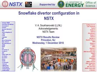
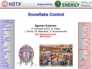
Snowflake Control
NSTX. Supported by. Snowflake Control. College W&M Colorado Sch Mines Columbia U CompX General Atomics INL Johns Hopkins U LANL LLNL Lodestar MIT Nova Photonics New York U Old Dominion U ORNL PPPL PSI Princeton U Purdue U SNL Think Tank, Inc. UC Davis UC Irvine UCLA UCSD

Snowflake Control
E N D
Presentation Transcript
NSTX Supported by Snowflake Control College W&M Colorado Sch Mines Columbia U CompX General Atomics INL Johns Hopkins U LANL LLNL Lodestar MIT Nova Photonics New York U Old Dominion U ORNL PPPL PSI Princeton U Purdue U SNL Think Tank, Inc. UC Davis UC Irvine UCLA UCSD U Colorado U Illinois U Maryland U Rochester U Washington U Wisconsin Culham Sci Ctr U St. Andrews York U Chubu U Fukui U Hiroshima U Hyogo U Kyoto U Kyushu U Kyushu Tokai U NIFS Niigata U U Tokyo JAEA Hebrew U Ioffe Inst RRC Kurchatov Inst TRINITI KBSI KAIST POSTECH ASIPP ENEA, Frascati CEA, Cadarache IPP, Jülich IPP, Garching ASCR, Czech Rep U Quebec Egemen Kolemen S. Gerhardt and D. A. Gates J. Ferron, M. Makowski, V. Soukhanovskii 2011 Research Forum Mar/16/2011
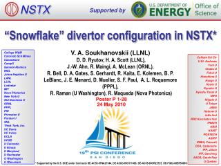
Snow Flake • “Snowflake” divertor configuration, a second-order null is created in the divertor region by placing two X-points in close proximity to each other. • This configuration has higher divertor flux expansion and different edge turbulence and magnetic shear properties, beneficial for divertor heat flux reduction, and possible “control” of turbulence and ELMs. • Implemented and used inner/outer strike point control to test the “snowflake” configuration. Vlad Soukhanovskii Example "snowflake" divertor configuration in NSTX.
Finding the 2nd X-point (In collaboration with Ferron, Makowski) • C code already developed for PCS • Locally expand of the Grad-Shafranov equation in toroidal coordinates: • Keep the 3rd order terms and find the magnetic nulls • Find coefficients from sample points • Very fast algorithm with reasonable accuracy. • J. Ferron from GA will add this C code algorithm in the general PCS.
Snow Flake Control • Locations of the X-points feedback-control • System Id: • Utilize Toksys to find the effect of PF1AL, PF1BL, PF2L coils on the separation of the two X-points. • Use the new relay feedback system ID in PCS. • The aim of the control: • Primary aim is the distance between the two X-points. • Secondary aim relative angle between the X-points. • Actuator: PF1B as the primary controller, PF1A/2 secondary • PF1B is a very effective coil in moving the secondary X-point • Not used in any other control loop • MIMO using PF1A, PF1B and PF2L will be probably be obtain control objective.
Control the 2nd X-point (In collaboration with Ferron, Makowski) • Add this fast algorithm with reasonable accuracy in PCS. • Control both the location of the X-points with PF coils. • Need 4 independent actuators for full control • Optimal use of the capability we have 2 or 3 PF coils (PF1AL-2L and sometimes PF1B) • Control the best combination of properties of interest (Relative distance/angle between the X-points…) • After lower snowflake divertor, extend this algorithm to control the upper snowflake configuration as well. • Time Requested 1 day.
NSTX Supported by XMP: Commissioning of the New PCS Phase Transition Fix for X-Point Height Control College W&M Colorado Sch Mines Columbia U CompX General Atomics INL Johns Hopkins U LANL LLNL Lodestar MIT Nova Photonics New York U Old Dominion U ORNL PPPL PSI Princeton U Purdue U SNL Think Tank, Inc. UC Davis UC Irvine UCLA UCSD U Colorado U Illinois U Maryland U Rochester U Washington U Wisconsin Culham Sci Ctr U St. Andrews York U Chubu U Fukui U Hiroshima U Hyogo U Kyoto U Kyushu U Kyushu Tokai U NIFS Niigata U U Tokyo JAEA Hebrew U Ioffe Inst RRC Kurchatov Inst TRINITI KBSI KAIST POSTECH ASIPP ENEA, Frascati CEA, Cadarache IPP, Jülich IPP, Garching ASCR, Czech Rep U Quebec Egemen Kolemen S. Gerhardt and D. A. Gates 2011 Research Forum Mar/16/2011
Successful Developed Combined X-point Height / SP Control • Tuned via Relay-Feedback. • Achieved RMS <1 cm X-point height error and <2 cm SP. • Scenario used for LLD experiments. Evolution of Plasma Boundary: X-point height roughly constant as OSP ramps
Handoff/Transition Issue • Currently we can’t start a control at flat-top. We can only start the control during the transition phase, 70 to 200 ms. • Took a long time hand tune the beginning of these shots. • Many people want to use the X-point/SP control but don’t want to spend their XP time to tune the transition • We want to be able to start any control at a given equilibrium. For day-to-day operations, this corresponds to starting strike-point, squareness, x-point etc. controls at the flat-top of the fiducial.
For 2011: Solution to “Hand-off” Problem • Problem when changing between control phases. • Normal Control has two parts: • Trajectory control: Scenario Development • Ex: Fiducial Shot, Isolver developed rough equilibrium, reload a shot that was developed before • Feedback control: Starting from the Scenario Shot, controlling parameters close to the defined values. • Need: Ability to add these two waveforms. • Simply be able to add PID output to the Voltage from the last phase. • V = V_equilibrium (flat-top) + PID(error). • Then, we will avoid “hand-off” problem
XMP: Commissioning of the New PCS Phase Transition Fix for X-Point Height Control • We are upgrading the PCS to transition as we like between phases. • XMP Time Request ½-1 day. • Test that this code is working properly. • Load a X-point Height / SP Control shot. • Start the control at flat-top instead of during the transition. • After fixing possible anomalies for the phase transition, commission the new capability.
NSTX Supported by Development and Performance of Model-Based Multi-Input-Multi-Output (MIMO) Shape Controllers College W&M Colorado Sch Mines Columbia U CompX General Atomics INL Johns Hopkins U LANL LLNL Lodestar MIT Nova Photonics New York U Old Dominion U ORNL PPPL PSI Princeton U Purdue U SNL Think Tank, Inc. UC Davis UC Irvine UCLA UCSD U Colorado U Illinois U Maryland U Rochester U Washington U Wisconsin Culham Sci Ctr U St. Andrews York U Chubu U Fukui U Hiroshima U Hyogo U Kyoto U Kyushu U Kyushu Tokai U NIFS Niigata U U Tokyo JAEA Hebrew U Ioffe Inst RRC Kurchatov Inst TRINITI KBSI KAIST POSTECH ASIPP ENEA, Frascati CEA, Cadarache IPP, Jülich IPP, Garching ASCR, Czech Rep U Quebec Egemen Kolemen D. Humphreys, M. Walker, S. Gerhardt and D. A. Gates 2011 Research Forum Mar/16/2011
Move from Current Single Input Single Out (SISO) Controlto MIMO Control • Currently each PF coil is used for a single control purpose via a single segment. • Problem: • NSTX-U will be running with taller and higher aspect ratio plasmas. I.e. less vertically stable. Need better coordination between various control efforts specially for the bottom/top gap. • Inner gap does not have a PF coil to control. • Many control segments are effected by the PF coil that does not control it. • No bottom/top gap control segment (We use X-point/SP control segments instead) • Solution: • Use all the segments (add a bottom/top gap segment) together in MIMO control. • To priorities some segments put a weight vector • Employ Toksys Model to develop and test the control in closed loop mode.
Full Multiple-Input-Multiple-Output (MIMO) Control • Use all the PF coils to control the plasma shape together. -Inner Gap -Lower Inner Strike Point -Vertical Position -Squareness Upper X-point Height …
Background • This is ITER CC (ITPA task MDC-18) and also an ASC proposal. • Model-Based Shape Control: • Designed based on linear models of plasma/conductor system response • Selected as basis for ITER control • Necessary to minimize need for experimental time to derive and tune control gains • Never used routinely on any operating device • Infrastructure for NSTX design is mature: • Electromagnetic system models, plasma response models well established • Some further validation needed (particularly power supply models) • PCS in common between DIII-D and NSTX enables common use of RTEFIT/isoflux control scheme, design for PID/Matrix gains
Proposal • Goals of experiment: • Continue development of model based controllers for NSTX • Study performance of 1st generation RTEFIT/isoflux multivariable (fully-populated) gain matrices for shape control in NSTX • Quantify improvement in shape control performance, validate model calculations • Perform shape command perturbations to study dynamic response • Assess interactions, diagonalization of commands: • Steps in vertical command • Regulation of X-points • Study controllability of inner gap
Experimental Approach • Time Request 1 day • Implement designed controllers for RTEFIT/isoflux • One or two target equilibria (Use the fiducial) • Highly reproducible, well-studied shape control target for comparison • Piggybacks to complete validation data needed • Employ Toksys Closed Loop with PCS to test and validate. • Apply step commands and/or relay feedback mode in closed loop: • Compare dynamic closed loop response with standard gains to new gains • Triangle waveforms to quantify constant derivatives vs constant proportional signals • Change target kappa, inner gap, X-point height • Quantify robustness to varying equilibria • Apply similar or subset of perturbations
NSTX Supported by Real-time Toroidal Rotation Feedback Control College W&M Colorado Sch Mines Columbia U CompX General Atomics INL Johns Hopkins U LANL LLNL Lodestar MIT Nova Photonics New York U Old Dominion U ORNL PPPL PSI Princeton U Purdue U SNL Think Tank, Inc. UC Davis UC Irvine UCLA UCSD U Colorado U Illinois U Maryland U Rochester U Washington U Wisconsin Culham Sci Ctr U St. Andrews York U Chubu U Fukui U Hiroshima U Hyogo U Kyoto U Kyushu U Kyushu Tokai U NIFS Niigata U U Tokyo JAEA Hebrew U Ioffe Inst RRC Kurchatov Inst TRINITI KBSI KAIST POSTECH ASIPP ENEA, Frascati CEA, Cadarache IPP, Jülich IPP, Garching ASCR, Czech Rep U Quebec Egemen Kolemen S. Gerhardt, M. Podesta and D. A. Gates 2011 Research Forum Mar/16/2011
Rotation Profile Control New 2nd NBI RTAN=110,120,130cm Present NBI RTAN=50,60,70cm Real time Rotation Measurement SS Vacuum Vessel Copper passive conductor plates BR Sensor BP Sensor 6 ex-vessel midplane control coils NSTX NB and Non-Axisymmetric Coil Actuators Currently installing the Real-Time Rotation Diagnostic Control the toroidal rotation of plasma in NSTX via this diagnostic Aim: To attain a desirable temporal & spatial profile Rotation profile: rotation shear get rid off micro instabilities small scale eddies (turbulence) Also, suppresses long wavelength instabilities – eddy currents
Governing Equations Temporal change Diffusion Pinch Ignore for initial analysis Torque input Loss (charge ex, ripple) 0 Also, temporal changes are small, ignored. Toroidal momentum balance (Goldston, 1986)
Model Equations • Toroidal momentum balance • 1D Linear PDE (parabolic) – diffusion equation with forcing • Neumann (r=0) and Dirichlet (r=1) BCs • Curve fit coefficients (3 shape variables , , ) • Coefficients to be supplied from TRANSP: and
Model Comparison with Experiment Experiment Model H- to L-mode transition center edge Numerically solved the reduced order PDE using adaptive time steps (parabolic PDE solver)
Model Comparison with Experiment H- to L-mode transition
Beam Torque Model (a) Shot number 120001 (unpulsed) (b) Shot number 128020 (pulsed) T(t,)/maxT(t,r) Ratio of the TNBI to maximum spatial TNBI at each time point is roughly a Gaussian distribution. Separated Neutral Beam Torque in two parts, spacial and time dependent.
Beam Torque Model Model versus data for Torque profile Time dependent part can be modeled as first order order differential equation with Ip as the forcing function
Neoclassical Toroidal Viscosity • Motivation: Use NTV torque to control Edge Rotation • Analyzing TRANSP outputs for various shots to find a simplified torque model for the neo-classical effect of the 3D coils. • Simple model as • Need updating after SPA-U in piggy-back mode.
Optimal Control for Rotation Profile Optimal control with full state control Converted PDE to ODE for control purpose Solve the optimization problem to minimize the cost function The feedback control law that minimizes is given by differential Riccati equation. Example shows where an average of 10% change in is requested to be achieves in 20 ms.
XP Prerequisites/Time Request • Time Request 1 day. • Before the XP, We expect to do offline analysis in the piggyback mode while other experiments are running and test the control algorithm in the Toksys close loop simulation. • Prerequisite: • Update PCS to take the rotation measurements. • Add a new control in PCS to take these measurements and use it to control the beam and SPAs • Beam control is similar to BetaN control, SPAs will need to be added. • In the XP • Test the Beam control of rotation magnitude. • Test the RWM coils to change the rotation gradient at the edge of the plasma. • Finally, we combine these two sets of actuators to control the full rotation profile.