Download
1 / 28
280 likes | 595 Vues
Computer Graphics Laboratory – 234326 Winter 2007-2008. Non-Realistic Rendering Photo Laborer. By Milena Natanov Supervised by Gershon Elber. Agenda. About Non-Realistic Rendering About Photo Laborer Photo Laborer Terms Photo Laborer Design and Implementation Possible extensions Results.

E N D
Computer Graphics Laboratory – 234326 Winter 2007-2008 Non-Realistic RenderingPhoto Laborer By Milena NatanovSupervised by Gershon Elber
Agenda • About Non-Realistic Rendering • About Photo Laborer • Photo Laborer Terms • Photo Laborer Design and Implementation • Possible extensions • Results
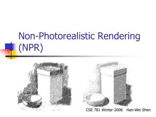
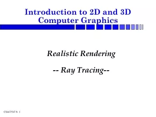
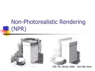
About Non-Realistic Rendering Non-photorealistic rendering (NPR) is an area of computer graphics that focuses on enabling a wide variety of expressive styles for digital art and producing “drawn by hand” images using computer.
About Non-Realistic Rendering “Illustrations have many advantages over Photorealism: • Focusing attention • Clarifying & simplifying shapes • Exposing parts that are hidden • Sketching/Illustrating approximate ideas • Conveying mood and emotion • Art, beauty, expression” Aaron Hertzmann
“Paint by Relaxation” This project is based on the work Paint by Relaxation published by Aaron Hertzmann in May 2000. Main aspects this research is focused on: • Input: photo created by digital camera • Output: image painted by artist • The painted image is created from the original image by adding “strokes” to the clean “canvas” • The painted image created with minimal energy cost • Painting style varies in accordance to different parameters user defines.
About Photo Laborer Photo Laborer implements the ideas presented in “Paint by Relaxation” research, with few changes: • Output image is built adding strokes on clean, white canvas • Several painting styles supported built-in (Realism, Watercolor, etc…), user can define custom styles • Processing time: several minutes for 800x600 image! • The research mentions that paint time takes hours. • Easy Graphical User Interface, includes user manual • User can re-paint specific areas with different painting styles • User can add custom strokes
Photo Laborer Terms - Brush • A brush is a real ‘brush’ stamp on the paper in specific point on the canvas. In the current Photo Laborer version, brush is characterized by: • brush min and max radius (width = radius * 2 + 1) • color texture (solid or with dark and bright lines) • In this version, user can control the width and the darkness/brightness deviation of the brush’s color • Customized brushes can be added in the future improvements
Photo Laborer Terms - Stroke • A stroke is a thick curve defined by a list of control points, curvature, and the brush selected for it. • Control points are than fine-tuned into thin (one-pixel) line using cardinal curve algorithm, forming stroke’s backbone. • Stroke is drawn by ‘moving’ the brush over the backbone pixels • Each move will print the brush’s texture on the canvas • Each ‘texture’ is rotated by the appropriate angle to give the stroke ‘real look’ • User can add custom strokes using GUI by selecting the control points
Photo Laborer Terms – Painted Image • Painted imageis defined as a collection of brush strokes. The painted image’s size is the same as the size of the original image. • A painting is rendered by compositing the brush strokes in order they appear onto the canvas • User sees the changes during the processing time and can cancel the operation in the middle
Photo Laborer Terms – Energy • Ideally, each stroke should consist of pixels that have similar or almost similar hue. Energy difference between two colors is Euclidean distance between RGB values of these colors: • sqrt(redDiff2*greenDiff2*blueDiff2) • Photo Laborer uses this formula to calculate the ‘quality’ of the stroke which is defined as an average energy difference of stroke colors with original colors on the image • Photo Laborer also uses energy difference to improve stroke building algorithms – details are described in the next slides
Photo Laborer Terms – Direction To speed up processing time and increase the quality of created strokes, Photo Laborer tries to build strokes that match the image contours Photo Laborer searches for object contours on the image (using special heuristics described later) and associates suggested Direction with each pixel identified as a contour Later, when stroke points are selected, Photo Laborer uses the direction information to make the stroke compliment object’s contour
Photo Laborer Implementation • Photo Laborer application is implemented in C++ • Development environment: Visual Studio 2005 • Libraries used: • wxWidgets: GUI, Image processing, XML, threads • I used latest version available on the web: 2.8.9 • Standard Template Library: <vector>, <algorithm>, etc… • Tested on Windows XP and Vista • The code does not use any Windows-specific API, so it can be recompiled and adjusted for use on any platform supported by wxWidgets
Photo Laborer Components Each component is described later in details. • GUI components • Main Frame, Photo Control, Paint Style Dialog • Logic components • Image Processor, Image Energy • Paint Style Manager • Building blocks • Paint Brush and Texture, Paint Style • Helper classes • Shape Algorithms , Direction, Randomizer, Worker Thread
Graphical User Interface (GUI) • Main Frame • Navigation menu • Toolbar menu • Original image • Painted image (also user can see energy or direction tables) • Photo Control • Displays the image (original, painted, tables) • Allows painting area and stroke points selection • Paint Style Dialog • View styles and their parameters • Add new, edit or delete existing styles
Logic Components • Image Processor and Image Energy • Hold energy table, per-pixel information (color and suggested direction, if any) • Implement the main ‘painting’ functionality • Paint Image / Area, Add Stroke, etc… • Paint Style Manager • Loads / Saves paint styles from / to XML that resides in user profile’s folder
Building Blocks • Paint Texture • Stroke’s stamp on the canvas: • list of pixel, each one holds color’s strength (bright/dark) and coordinates relative to texture’s center • Paint Brush • Define how the brush’s stamp (texture) looks like for each radius and angle • Photo Laborer supports two kinds of brushes: • Solid brush: generates 3-pixels wide textures with same color • Random brush: creates dark or bright lines within the texture • Cache – for fast performance, this class caches the textures for each angle/radius pair • Paint Style • Defines style parameters (such as maximal stroke length) • Photo Laborer comes with several built-in styles, user can add custom ones
Photo Laborer Algorithms The main data structures and algorithms Photo Laborer is based on are: Energy table Direction table Stroke creation Stroke rendering on the painted imagery
Energy Table Energy table describes the energy of each pixel relative to its neighbors. Neighbors are defined by the stroke average radius (width = radius*2 + 1): pixels on the circle with this radius are used as a neighbors. This table is pre-computed before painting. It used for two purposes: Selecting the next stroke ‘start point’. Low energy points have better change to match the image thus they are selected first. Calculate direction table.
Direction Table Direction table aims in creating strokes that match the contours on the image. When stroke control points are selected, Direction table is used to check the location of the next control point. This table is calculated before painting process starts Special heuristic algorithm based on energy table is used to calculate whether or not the pixel is on contour, and, if yes, tangent is calculated and saved in Direction table.
Stroke Creation Choose the next non-covered pixel from the list of non-covered pixels sorted by their energy (from low energy to high). This pixel is the first control point of the new stroke. Choose the rest control points using direction table or randomly if direction is not available Build the stroke (cardinal curve) over the control points according to user’s style (length, curvature parameters). Stroke’s backbone:
Stroke Creation cont. For each pixel in stroke’s backbone line, apply brush’s texture on it Brush texture is created from brush texture image, rotated by tangent of the current pixel. Rotated textures: Rotated textures are cachedfor fast performance after the creation Resulted stroke: Current version supports darkening and brightening of the texture
Painting Style Painting style is defined by below parameters: Style name. Brush [minimal, maximal] radius, in pixels. Stroke [minimal, maximal] length, in pixels. Stroke curvature (maximal number of control points). Brightening/darkening of the main stroke’s color Built-in styles: Hyperrealism, Realism, Impressionism, Expressionism, Pointillist, Watercolor User can add custom styles
Possible extensions This system may have various nice features that can be added in the future in order to make it even more attractive: • Undo/Redo changes. • Rich stroke textures • User-provided textures • Textured canvas (background): wood, paper, silk, etc…