Download
1 / 30
350 likes | 562 Vues
Explore the momentum theory for propellers and understand how propulsive efficiency, thrust coefficient, and power coefficient influence propulsion systems. Learn about blade elements, pitch control, contra-rotating propellers, and propeller performance maps.

E N D
THEORY OF PROPULSION 9. Propellers P. M. SFORZA University of Florida
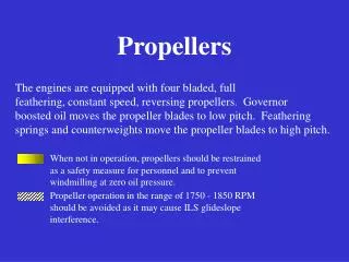
Momentum theory for propellers streamtube Thrust V0 Ve • The thrust is uniformly distributed over the disc • No rotation is imparted to the flow by the actuator disc • Streamtube entering and leaving defines the flow distinctly • Pressure far ahead and behind matches the ambient value Actuator disc Theory of Propulsion
Control volume for actuator disc Control volume p V0 p+Dp Ve V0 F r R Disc of area A Inflow along horizontal boundaries Theory of Propulsion
Conservation of mass in the C.V. Volume flow into the C.V. through the horizontal boundaries of the C.V. Theory of Propulsion
Momentum conservation in the C.V. Momentum out of C.V. Momentum into C.V. Force on the fluid Theory of Propulsion
Bernoulli’s Eq.- up and downstream disc Up: V1 p p+Dp Down: Pressure jump Continuity requires that p r2Ve=AV1 And therefore Theory of Propulsion
Velocity induced by actuator disc V’=V1-V0is called the induced velocity and the thrust is Thrust = (mass through disc) (overall change in velocity) Theory of Propulsion
Conservation of energy inthe C.V. The power absorbed by the fluid is Theory of Propulsion
Ideal propulsive efficiency In terms of the induced velocity the power absorbed is power required to keep V=V0 The ideal propulsive efficiency is then Theory of Propulsion
1.0 0.8 Ideal propulsive efficiency hi 0.4 0.2 0 0 0.1 0.2 0.3 0.4 V’/V0 Operating range V0 V’ V1=Vavg=V0+V’ Theory of Propulsion
Thrust coefficient The thrust coefficient, which is dimensionless, is defined as Disc loading Theory of Propulsion
Power coefficient NOTE: For a statically thrusting propeller V0=0 and the non-dimensional coefficients don’t apply. Instead, Theory of Propulsion
Thrust variation with flight speed Equating the power to the propeller for the moving and static cases yields: This equation may be put in the following form: Theory of Propulsion
1.0 Thrust variation with flight speed F/Fstatic V’static=(Fstatic/2rA)1/2 0 1 0 V0/V’static Note that thrust drops as speed increases Theory of Propulsion
Force and velocity on blade element dL f+ai V’ Ve f ai V0 VR f wr dD Axis of rotation Chord line dF Induced angle g Theory of Propulsion
The blade element for a propeller dr r Blade element Axis of rotation C(r) Theory of Propulsion
Thrust and power for a propeller The induced angle ai depends on the induced velocity V’ Theory of Propulsion
Propeller characteristics Blade activity factor (AF) is a measure of solidity and therefore power absorption capability constant chord blade c(r) r R Typical range: 100<AF<150 Theory of Propulsion
Geometric pitch g Advance during 1 revolution wr Axis of rotation 2p r tang Chord line g 2pr In-plane distance moved in 1 revolution Advance ratio J= V0 /wD g= blade pitch angle Theory of Propulsion
Coarse pitch operation V0 L F R wr g D Axis of rotation Chord line V0 High J: cruise Low J Theory of Propulsion
Fine pitch operation L F V0 R wr g D Axis of rotation Chord line V0 High J Low J: T-O Theory of Propulsion
The two-speed propeller h Coarse pitch Fine pitch 0 Advance ratio J 1 0 Theory of Propulsion
The constant speed propeller 1 h g3 g1 g2 g4 0 0 Advance ratio J g is varied to keep w constant at best engine speed Theory of Propulsion
Blade pitch control Use of pitch control. Credits - NASA Theory of Propulsion
Contra-rotating propellers Theory of Propulsion
Contra-rotating propellers Theory of Propulsion
Nondimensional blade parameters Advance ratio; J=V/nD Thrust coefficient: CT=F/rn2D4 Torque coefficient: Cq=Tq/rn2D5 Power coefficient: CP=P/rn3D5 Efficiency: h=JCT/CP Theory of Propulsion
Propeller performance map 0.7 CP h=88% 70% 85% 80% 30o g3c/4 =20o 40o 0 4 Advance ratio J 0 Power coefficient CP=P/rw3D5 Theory of Propulsion
Twist of propeller blades VR,tip VR,hub wrhub wrtip Theory of Propulsion