Download
1 / 8
80 likes | 276 Vues
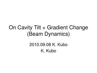
On Cavity Tilt + Gradient Change (Beam Dynamics). 2010.09.08 K. Kubo K. Kubo. Transverse effect of acc. field with cavity tilt. Acc. field E , length L, tilt angle q. beam. Transverse kick in the cavity: D pt = sin q eV. Edge (de)focus. exit. entrance. offset: y 0 -L sin q /2.

E N D
On Cavity Tilt + Gradient Change(Beam Dynamics) 2010.09.08 K. Kubo K. Kubo
Transverse effect of acc. field with cavity tilt Acc. field E, length L, tilt angle q beam Transverse kick in the cavity: Dpt = sinq eV Edge (de)focus exit entrance offset: y0-Lsinq /2 offset: y0+Lsinq /2 Transverse kick at the entrance: Dpt = -eE (y0+sinq L/2)/2 Transverse kick at the exit: Dpt = eE (y0-sinq L/2)/2 Total transverse kick by the cavity: Dpt = sinq eV/2
Cavity tilt change (vibration) and Fixed cavity tilt + voltage change have the same effect orbit and emittance • 3 micro-rad. tilt angle change, cavity to cavity random 0.8-sigma orbit change at the end of main linac 0.5 nm (2.5%) emittance growth • Assuming fixed tilt angle (misalignment) RMS 300 micro-rad. 1% voltage change, cavity to cavity random Same as above. • RF control stabilizes vector sum, not voltage of each cavity. • Cavities with different coupling, fed by one RF source. voltage change during one pulse. • Different detuning (pulse to pulse) pulse to pulse voltage change
1 klystron to 2 cavities 1 2 RF control will keep total voltage flat. But, total transverse kick may change. total 1 1 Transverse kick total Vc 2 time 2 time
Orbit jitter sources in ML Tolerances, tolerable timescale depend on feedback performance.
Result of simulation Cavity tilt change 15 urad, equivalent to Fixed 300 urad + 5% gradient change (numbers are RMS) Starting linac at different energies (to see effective ness of orbit correction) E.g. if orbit is corrected at 50 GeV, emittance growth will be ~ 1 nm from 15 to 50 GeV plus ~ 2.5 nm from 50 to 250 GeV Total 3.5 nm, instead of 11 nm without such correction.
Intra-pulse orbit correction will loosen the tolerance of pulse to pulse change? • If gradient change is same for all pulses • Orbit change is predictable and can be corrected. • If gradient change is a simple function of time. • Orbit of head part of a pulse can be used for prediction of orbit of following part. • Gradient change is slow (~ time constant of cavity filling time) • Intra-pulse feedback, similar to IP feedback (but ca be much slower), can be used. Probably possible. • Available space in ML?
Summary • Fast tilt change should be < 3 urad (mechanical motion) • (Fixed tilt) x (Relative gradient change of each cavity) should be < 3 urad • If gradient change is predicted, or slow enough, intra-pulse orbit correction will loosen the tolerance. We assume fixed cavity tilt 300 urad, then, gradient of each cavity flatness in a pulse should be (roughly) • < 1% for pulse to pulse without intra-pulse correction • < 5 % with intra-pulse correction (Numbers are RMS)