Artistic Image Generation By Deviation Mapping
Artistic Image Generation By Deviation Mapping. Liu Wenyin Xin Tong Xu Yingqing Heung-Yeung Shum (Microsoft Research) Zhong Hua (Carnegie Mellon University). IJIG 2001 (International Journal of Image and Graphics). Introduction.

Artistic Image Generation By Deviation Mapping
E N D
Presentation Transcript
Artistic Image Generation By Deviation Mapping Liu WenyinXin TongXu YingqingHeung-Yeung Shum(Microsoft Research) Zhong Hua(Carnegie Mellon University) IJIG 2001(International Journal of Image and Graphics)
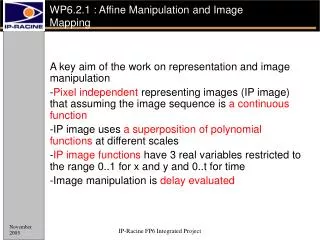
Introduction • A novel technique (deviation mapping) that generates images with artistic appearances • ex: spray painted wall, embossment, cashmere painting • Deviation map: constructed from a background image • Instead of recovering the exact geometry from the background image, the deviation map can be regarded as a virtual surface • This virtual surface is then painted with a foreground image and illuminated to generate the final result
Introduction • Traditional synthesis methods • pixel-wise operation • window operation • If geometrical and photometric models of scenes or objects are know, one can always render an image given the lighting conditions • not for image synthesis and do not apply for single image input
Deviation Mapping • Similar to the bump mapping approach • Not a technique for 3D rendering but for image processing only • Under some assumption of the lighting conditions, each pixel of the deviation map can be directly represented as a single deviation angle • intensity of background image 0-255 → 90-0 degrees of the deviation angle
Re-lighting Special Effect Image Other Optional Processing Deviation Map(Virtual Surface) Background Image(Original Image 2 or an intermediate image yielded from Original Image 1) Deviation Map Generation Image Synthesis Method Foreground Image(Original Image 1)
: result image intensity: color channel: ambient light: light color: foreground image Illumination Model-Phong Model ambient diffuse specular
Deviation Mapping constant coefficient result image foreground deviation map
Result • PII-400 PC, 128MB memory < 1 second • Very fast & simple + =
Result + =
Result + =
projector function converts reflection vector (x,y,z)to texture image (u,v) r viewer v Environment Mapping (EM) • Also called “reflection mapping” • A simple & powerful method of generating approximations of reflections in curved surfaces n environment texture image reflective surface
Environment Mapping (EM) • The EM approximation assumes the objects and lights being reflected with EM are far away, and that the reflector will not reflect itself • If the assumptions hold, then the environment around the reflector can be treated as atwo-dimensional projection surrounding it
EM Algorithm • Generate a two-dimensional image of the environment (environment/reflection map) • Compute the normal at the location on the surface of the object • Compute the reflection vector from the view vector and the normal • Use the reflection vector to compute an index into the environment map (projector functions) • Use the texel data from the environment map to color the current pixel
Cubic Environment Mapping [1986] Greene • Environment map is obtained by • placing the camera in the center of the environment • projecting the environment onto the sides of a cube positioned with its center at the camera’s location
Cubic Environment Mapping • Used in many photorealistic system • Environment maps can be generated by the system itself easily, and could even be generated on the fly • The direction of the normalized reflection vector determines which face of the cube to use • e.g. the vector (-0.2, 0.5, -0.84) → select the –Z face • [-1, 1] → [0, 1] in order to compute the texture coordinates • (-0.2, 0.5) are mapped to((-0.2/0.84+1)/2, (0.5/0.84+1)/2) = (0.38, 0.80)
Bump Mapping • A technique that makes a surface uneven • Basic idea: modify the surface normal by accessing a texture • geometric normal of the surface remains the same • merely modify the normal used in the lighting equation • modify the normal per pixel changes the perception of the polygon surface itself • Two basic methods of modifying the normal with a bump map
Method 1 • Two signed values, bu and bv, at each point • bu and bv correspond to the amount along the u and v image axes by which to vary the normal • bu and bv essentially represent how steep the surface is and which way it faces at the point buu bvv n n’ bump texture (bu,bv)
Method 2 • Uses a height field to modify the surface normal’s direction • Each monochrome texture value represents a height (white→high, black→low) • Artifact • silhouettes of objects • shadow height field texel values
Normal Map • Instead of storing heights or slopes, the actual new normals for the surface are stored as (x,y,z) vectors in a normal map
Introduction • Despite their physical inaccuracy, simple models such as the Phong model remain popular • True photorealism, however, requires more sophisticated and elaborate model of surface properties • A truly complete representation of the reflective behavior of a surface might take into account such phenomena as • polarization, scattering, fluorescence, phosphorescence (might vary with position on the surface)
radiance BRDF = irradiance ( BRDF is expressed in units of “inverse steradians” (sr-1) ) BRDF • We are left with a reflectance function of the angles of the incident and reflected angles only • This function is called the Bidirectional Reflectance Distribution Function • Intuitively the BRDF represents, for each incoming angle, the amount of light that is scattered in each outgoing angle W/cm2 /sr W/cm2
BRDF • [White Papers: Glossary of Terms] • Bi-directional reflectance distribution function describes the directional distribution of reflected light. It is defined as the ratio of the radiance (luminance) of light reflected in the viewing direction and the irradiance (illuminance) from the incident direction. In the general case, it is a function of both incident and viewing directions.BRDF is expressed in units of inverse steradians.
Radiance & Irradiance • Radiance is a measure of radiometric flux density per unit solid angle. • Radiance is typically expressed in W/cm2 /sr (watts per square centimeter per steradian). • Irradiance is a measure of radiometric fluxper unit area. • Irradiance is typically expressed in W/cm2 (watts per square centimeter).
Phong Model • A simple model that can be computed rapidly • Has three components • Diffuse • Specular • Ambient • Uses four vectors • To source • To viewer • Normal • Perfect reflector
Ambient Reflection • The intensity of ambient light La is thesame at every point on the surface • The amount reflected is given by the ambient reflection coefficient ka
n l p Diffuse Reflection • A perfectly diffuse reflector scatters the light that it reflects equally in all direction • Such a surface appear the same to all viewers
cosaf 90 -90 f Specular Reflection • A diffuse surface is rough,a specular surface is smooth • we consider the surface as being rough for the diffuse term and smooth for the specular term f (shininess coefficient)