June 2008
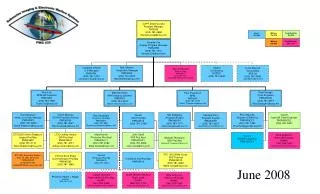
Introduction to iPECS P5 Hardware. June 2008. R&D Center / BCS HW Team. Contents. Design New Components Overview Structure of MB & PSU Signaling PSU Spec. Installation Main Cabinet Slot Number Back side of Main Cabinet RJ-21 pin Assignment RS-232 Cable for Monitoring 1URMB


June 2008
E N D
Presentation Transcript
Introduction to iPECS P5 Hardware June 2008 R&D Center / BCS HW Team
Contents • Design • New Components • Overview • Structure of MB & PSU • Signaling • PSU Spec. • Installation • Main Cabinet Slot Number • Back side of Main Cabinet • RJ-21 pin Assignment • RS-232 Cable for Monitoring • 1URMB • ANNEX 1. the change of Gateway package • ANNEX 2. the possibility of Power Jack problem
2. New Components Description Specification New Hardware PSU (AC/DC Power Supply Unit) Input : 100-240 VAC @ 50/60 Hz Output : -48 VDC @ 5.3 Amps, +5V @ 1 Amps New Cabinet Compact Cabinet with cover, built in DC-FAN RBKTE Rack Mount Bracket Kit for New Cabinet WBRKE Wall Mount Bracket for New Cabinet Line Connection between Gateway and Champ connector. MB1 MBE MB2 The Power(-48VDC) of PSU is supplied with Gateway. PSU Monitoring 1U BRACKET 1U 19” Rack Mounting Kit for Single GW Module Installation Decoration Front Panel Decorate the Front of LIK-SLTM32 *) P4 Gateway Modules – common use . New Components
3. Overview Overview • iPECS P4 Modules are used. • Compact Size Cabinet : 9 universal slots including MFIM100/300/600 • Central Power Supply via Backplane (LIK-MBE). • Power Redundancy using ORing Method : Optional. • Monitoring the status of PSU and FAN • Amphenol connectoron Backplane for Connection of the Telecommunication Line. • ( Exception : LAN Connection, WTIM4/8) • Improving the temperature of the Cabinet using two DC-FANs on the rear side. • 1U BRACKET : 1U 19” Rack Mounting Kit for Single GW Module.
4. Structure of MB & PSU PSU2 PSU1 Gateway FAN1 FAN2 48V 48V 5V FAN1 OK FAN1 OK FAN2 OK FAN2 OK MCU PSU2 Install PSU2 OK PSU2 FAN OK PSU1 Install SIO PSU1 OK PSU Monitoring PSU1 FAN OK 5V 5V Mother Board Power Redundancy
5. Signaling PSU Indicator PSU Signal To MB PSU Signal From MB PSU Inlet And Switch
6. PSU Spec. OUTPUT: -48VDC/250W
6. PSU Spec. • The Maximum current of PSU is 5.3A@-48Vdc. • DTIM8 and PoE8 have a limit of installation quantity. • The limit quantity of PoE8 with LIP is 6 per Cabinet. (** recommended quantity 5)
7. installation. 7.1. The Kinds of MCKTE Installation ① Desktop ② Rack Mount ③Wall Mount (MCKTE) (MCKTE+RBKTE) (MCKTE+WBRKE)
7. installation. 7.2. PSU Installation Main PSU Back-up PSU • LIK-PSU is consisted of PSU, two Brackets, four screws and Power Cord. • The Brackets are fixed to Main Cabinet with screws. • PSU is inserted into the Main Cabinet. • Slide the PSU into the Cabinet, engaging the connector of MB. • The captive Screws of PSU are tightened to the Brackets. • PSU is inserted into the Main Cabinet. • Slide the PSU into the Cabinet, engaging the connector of MB. • The captive Screws of PSU are tightened to the Brackets.
8. Main Cabinet Slot Number. SLOT3 SLOT4 SLOT5 SLOT6 SLOT8 SLOT9/ PSU2 SLOT1 SLOT2 SLOT7 PSU1
9. Back Side of Main Cabinet . FAN2 FAN1 26 1 26 1 26 1 26 1 26 1 FAN2 FAN1 50 25 50 25 50 25 50 25 50 25 LC5 LC4 LC3 LC2 LC1
: : 1 : : 9 1 : : 9 11. RS-232 cable for Monitoring. 11.1 Installation • The RS-232 cable is connected between a PSU and a gateway. • It will be delivered together with LIK-MCKTE • Programming via Web Adm. is required. 11.2 Cable spec. 9 Pin RS-232 Cable (1:1) female male - Length : 400 mm - Pin to Pin Connection wiring(1:1)
11. RS-232 cable for Monitoring. 11-3. Software Version The following SW version or later should be applied to monitor the status of Main Cabinet.
11. RS-232 cable for Monitoring. 11-4. Test Method (Example: in case of monitoring the status of a cabinet using LIK-SLTM8) 1. Connect a monitoring cable between RS-232 Connectors of a SLTM8 and a PSU. 2. Check the slot sequence of SLTM8 : PGM102-103
11. RS-232 cable for Monitoring. 3. Input the Cabinet Index. : PGM197 (Cabinet attributes) 4. Change the Cabinet Status Check value to “ON”. 5. Input the Status Check Gateway “4” (Slot sequence of SLTM8) and click the save button.
11. RS-232 cable for Monitoring. 6. The status check value of Cabinet “1” is changed following picture. PSU2 FAN
11. RS-232 cable for Monitoring. 7. Reload the Cabinet index “1”, then you can recognize the cabinet status. 1 PSU2 FAN * Cabinet Alarm Status : O(Normal), X(Fail), -(Not installed) 8. If the fail condition occurs, the attendant keyset gives the alarm ring.
12. 1URMB 1URMB Adapter Installation 1U-RMB Rack-mount Installation 1U-RMB Gateway Installation One rack unit is 44.45 mm (1.75 inch) high.
ANNEX 1: the change of Gateway Package After launching iPECS P5 (LIK-MCKTE, LIK-PSU..), the Gateway package will be changed and delivered as following. Gateway Gateway AC-DC Adaptor, Power code AC-DC Adaptor, Power code
PCB: Solder Side Power Jack Short circuit between Two terminal of Power Jack ANNEX 2: the possibility of Power Jack Problem When a Gateway is installed in P5 Cabinet, there may be no power feeding. No Present Problem / Customer Request Counter-plan Remark 1. When a Gateway is installed in P5 Cabinet, there may be no power feeding. 1. Power Jack of the Gateway has a problem in supplying the power from backplane because of the defective. In particular using adapter for a long time, it seems that all gateways may have a problem because of the defective Power Jack. Solution1) Replacing it with New Power Jack Solution2) It is easy to be adopted on the Field site. As following figure, There is a connection between V-_DIN and V-_PJ. In this case, during plugging in Adapter and using P5 cabinet, the power of PSU and one of adapter are provided to the gateway at the same time. But there is no damage. 1 V+ : Common use V-_DIN : Connected to DIN(MB) V-_PJ : Connected to Power Adapter [Fig. 1: Circuit Diagram of Power Jack ] [Fig. 2: Sectioned Drawing of Power Jack] [Fig. 3: Appearance of Power Jack] Above Fig. 1: The arrow of contact point 1. When DC Jack of power adaptor is connected, the arrow is off to the contact point, and the power of Adapter is supplied to GW. 2. When DC Jack of power adaptor is NOT connected, the arrow is ON to the contact point, and the power is supplied from DIN Connecter (PSU).