Download
1 / 56
560 likes | 797 Vues
Formal Approaches to Business Processes through Petri Nets. Nick Russell Arthur H. M. ter Hofstede. Acknowledgement. These slides summarize the content of Chapter 2 of the book: A.H.M. ter Hofstede, W. van der Aalst, M. Adams, N. Russell.

E N D
Formal Approaches to Business Processes through Petri Nets Nick Russell Arthur H. M. terHofstede
Acknowledgement These slides summarize the content of Chapter 2 of the book: A.H.M. ter Hofstede, W. van der Aalst, M. Adams, N. Russell. Modern Business Process Automation. YAWL and its support environment.Springer, 2010. These slides have been prepared by or inspired by slides of the following people: • Wil van der Aalst, TUE & QUT • Michael Adams, QUT • Lachlan Aldred, QUT • BartekKiepuszewski, Moreton, BMS, Cutter Consortium • Marcello La Rosa, QUT • PetiaWohed, SU/KTH • Moe Wynn, QUT
Introduction • One of the frequent criticisms of modeling notations is that they are impreciseand, as a consequence, subject to varying interpretations by different parties. • Describing a candidate modeling notation in terms of a formal technique provides an effective means of minimizing the potential for ambiguity. • To do so, it is necessary to describe both the syntax and semantics of the modeling formalism using a well-founded technique. • Suitable techniques for doing so generally stem from mathematical foundations and include general-purpose modeling approaches such as Petri nets.
Petri Nets • Petri nets have proven to be a particularly effective mechanism for modeling the dynamic aspects of processes. • Petri Nets they have three specific advantages: • Formal semantics despite the graphical nature. • State-based instead of event-based. • Abundance of analysis techniques. • Many variant exist: we will analyze workflow nets and reset nets. • Petri Nets have been chosen as the formal underpinning for the YAWLlanguage(it will be discussed in an upcoming lecture).
Overview Formal foundations for modeling languages in BPM Petri nets Some fundamental results Workflow nets Mapping workflow concepts to Petri nets Reset nets
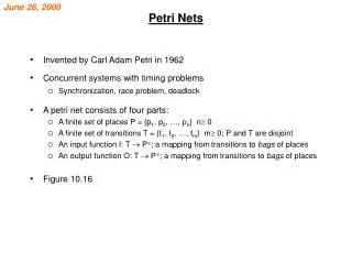
Petri Nets • Originate from C.A. Petri’s PhD thesis (1962). • They were originally conceived as a technique for the description and analysis of concurrent behaviour in distributed systems. • Based on a few simple concepts, yet expressive. • They have a simple graphical formatand a precise operational semantics that makes them an attractive option for modeling the static and dynamic aspects of processes. • Many analysis techniques exist. • Many extensions and variants have been defined over the years.
Applications • Applications in many different areas, such as databases, software engineering, formal semantics, etc. • There are two main uses of Petri nets for workflows: • Specifications of workflows. • Formal foundation for workflows (semantics, analysis of properties).
Petri Nets: Basics • A Petri Net takes the form of a directed bipartite graph where the nodes are either places or transitions. • Places represent intermediate states that may exist during the operation of a process. Places are represented by circles. • Places can be input/output of transitions. Transitions correspond to the activities or events of which the process is made up. Transitions are represented by rectangles or thick bars. • Arcs connect places and transitions in a way that places can only be connected to transitions and vice-versa. or arc place transition
Petri Nets: Definition • Formally a Petri net N is a triple (P, T, F) where • P is a finite set of places • T is a finite set of transitions where P ∩ T = • F (P x T T x P) is the set of arcs known as the flow relation • A directed arc from a place p to a transition t indicates that p is an input place of t. Formally: • t = {p P | (p, t) F} • A directed arc from a transition tto a place p indicates that p is an output place of t. Formally: • t = {p P | (t, p) F} • With an analogous meaning, we can define: • p = {t T | (p, t) F} and p = {t T | (t, p) F}
Petri Net: Example P = {p1, p2, p3, p4} T = {t1, t2, t3} F = {(p1, t1), (p2, t1), (t1, p3), (p2, t2), (t2, p4), (p4, t3), (t3,p2)} t1 = {p3}; t1 = {p1, p2}; p2 = {t3}; p1 = ; p2 = {t1, t2} t1 p1 p3 t2 p4 p2 t3
Petri Nets: Example p1 p2 t2 p3 t3 t1 P = ... T = … F = ... t1 = …… ; t1 = …… ; p2 = …… ; p2 = ......
Markings • The operational semantics of a Petri Net is described in terms of particular marks called tokens(graphically represented as black dots ). • Places in Petri Nets can contain any number of tokens. The distribution of tokens across all of the places in a net is called a marking. For a Petri net an initial marking M0 needs to be specified. • Marking assigns tokens to places; formally, a marking M of a Petri net N = (P,T,F) is a function M: P -> NAT. • The marking below is formally captured by the following marking M = {(p1,1),(p2,2),(p3,0)}. p1 p2 p3
State of a Petri Net • A state can be compactly described as shown in the following example: • 1p1+2p2 + 0p3 is the state with one token in place p1, two tokens in p2 and no tokens in p3. • We can also represent this state in the following (equivalent) way: p1+2p2. • We can also describe an ordering function ≥ over the set of possible states such that, given aPetri net N = (P,T,F) and markings M and M′, M ≥ M′ iff for all p in P: M(p) ≥ M′(p). M > M′ iff M ≥ M′ and M ≠ M′. p1 p2 p3
Enabled Transitions • The operational semantics of Petri nets are characterized by the notion of a transition executing or “firing”. A transition in a Petri net can “fire” whenever there are one or more tokens in each of its input places. • The execution of a transition occurs in accordance with the following firing rules: • A transition t is said to be enabled if and only if each input place p of t contains at least one token. Only enabled transitions may fire. • Formally, a transition t is enabled in a marking M iff for each p, with p •t, M(p) > 0. (see definition 2.7 of [DE95]) • If transition t fires, then t consumes one token from each input place p of t and produces one token for each output place p of t . p1 p1 t1 p3 p3 T1 isnot enabled! T1 is enabled and mayfire! p2 p2 t1 p1 p3 • T1 fires! When a transition fires, the marking and the state of the Petri Net change. p2 t1
Firing a Transition: Example AFTER BEFORE
Firing Transitions: Further Examples • It is assumed that the firing of a transition is an atomic action that occurs instantaneously and cannot be interrupted. • If there are multiple enabled transitions, any one of them may fire; however, for execution purposes, it is assumed that they cannot fire simultaneously. • An enabled transition is not forced to fire immediately but can do so at a time of its choosing. • These features make Petri nets particularly suitable for modeling concurrent process executions.
Firing Transitions • Given a Petri Net (P,T,F) and an initial state M, we have the following notations that characterize the firing of a given transition t: • M t M′ indicates that if transition t is enabled in state M, then firing t in M results in state M’. Formally, notation M t M′, is defined by: • M′(p) = M(p) if p •t t• or p •t t• • M′(p) = M(p) - 1 if p •t and p t• • M′(p) = M(p) + 1 if p t• and p •t • M M′ indicates that there is a transition t such that M t M′. • M M′ denotes the firing sequence = t0 t1… tn-1 that leads from state M to state M’, such that M = M0t0M1t1 M2 … Mn-1 tn-1Mn = M′ Note that the transitions do not have to be different! • A state M’ is called reachable from state M (we write M * M′) iff there is a firing sequence that leads from state M to state M’. • Informally, a marking is reachable from another marking if there is a sequence of transitions that can fire from the first marking to arrive at the second marking.
Petri nets: Order Fulfillment Example If the customerhasnotsufficient credit the declineorderruns and, finally, the return stock task ensuresthat the items from the order are returned to the warehouse. Whenpack orderandcheckaccount taskshavebeenbothcompleted, the credit check task isexecuted. First, a take ordertask isexecuted. If the customerhassufficient credit remaining, the orderisdespatched. Then, pack orderandcheck account tasks are executed in parallel.
Petri nets: Example of a vending machine (source [DE95] p. 4) ready for insertion candy storage insert coin refill dispense candy reject coin holding coin accept coin request for refill ready to dispense
ready for insertion candy storage insert coin refill dispense candy reject coin holding coin accept coin request for refill ready to dispense
Petri net example: Elevator 1 Animation by Wil van der Aalst, Vincent Almering and HermanWijbenga
Petri net example: Elevator 2 Animation by Wil van der Aalst, Vincent Almering and HermanWijbenga
Petri net example: Elevator 3 Animation by Wil van der Aalst, Vincent Almering and HermanWijbenga
Modelling Exercise • We want to model with a Petri Net the behaviour of two traffic lights at an intersection, in a way that they cannot be green or yellow at the same time. • Conversely, they are allowed to signal red at the same time.
Solution Traffic Lights Animation by Wil van der Aalst, Vincent Almering and HermanWijbenga
Homeworks • Two traffic lights at an intersection. If one is red, the other should be green etc. (many discussions on modelling traffic lights through Petri nets can be found on the internet). • A producer and a consumer producing and consuming (resp.) indefinitely. The consumer cannot consume more than the producer has produced thus far. How does your model change if the buffer between them is of limited size? (this is a well-known concurrency problem) • Two parallel processes with two critical sections. If one of the two processes is in its critical section, the other process should not be able to enter its critical section and vice versa. (this is also a well-known concurrency problem)
Coverable Markings • Coverability is a weaker notion than reachability. A marking M is coverableiff a reachable marking M′ exists such that M′ ≥ M (see e.g. Definition 5 in [HAAR09]). • Example: Given the Petri net and marking in figure, p1+p2+p3 is a reachable marking, while p1+p3 is a coverable marking (but not reachable). • To decide whether a given marking M is reachable is a DSPACE(exp)-hard problem. t1 t2 p1 p2 p3
Properties • A Petri net N with initial marking M0 is liveiff for every reachable marking M and every transition t there exists a marking M’ reachable from M which enables t. (see definition 2.16 of [DE95]). • More informally: A Petri net with initial marking M0 is live if, no matter what marking has been reached from M0, it is possible to ultimately fire any transition by progressing through some further firing sequence. • The notion of liveness is important since it demonstrates that at least one transition can fire in every reachable state. A live Petri net guarantees deadlock-free operation. • A Petri net N with initial marking M0 is deadlock freeiff every reachable marking enables some transition (see definition 2.16 of [DE95]).
Properties • A Petri net N with initial marking M0 is k-boundediff for every reachable marking M, M(p) k (k is the minimal number for which this holds). (see definition 2.20 of [DE95]). • A 1-bounded net is called safe. • The property of boundnessensures that the number of tokens cannot grow arbitrarily. • A Petri net N is strongly connectediff for every pair of nodes (places or transitions) x and y there is a path from x to y and vice-versa.
Isthis Petri Net live and bounded? t1 p3 t3 t4 p2 p1 p4 t2 M0 = (1,0,0,1) M1 = (0,1,0,1) M2 = (0,0,1,0) M3 = (0,0,0,1) A bounded but non-live Petri net
Isthis Petri Net live and bounded? M1 = (0, 1, 1, 0, 0) M2 = (0, 0, 0, 1, 1) M3 = (1, 1, 0, 0, 0) M4 = (0, 2, 1, 0, 0) M0 = (1, 0, 0, 0, 0) p1 t1 p2 p3 t2 t3 p4 p5 t4 An unbounded but live Petri net
Exercise • Is the vending machine live? • Is it deadlock free? • Is it bounded? • Is it strongly connected? • Can a marking be reached with tokens both in “ready for insertion” and “ready to dispense”? • Give an example of a marking that is coverable but not reachable.
Free Choice Petri nets • Many verification problems in Petri nets have a high complexity. • Free Choice Petri nets are a subclass of Petri nets with a “nice” tradeoff between expressiveness and analyzability (see e.g. [DE95]). • All elementary workflow concepts are essentially free choice. • In a Free Choice Petri net “the result of the choice between two transitions can never be influenced by the rest of the system” [DE95]
Free Choice Petri nets: Definition(see [DE95] p63-64) • In a Free Choice Petri net, every pair of transitions either share all their input places, or they share none. • Formally, a Petri net N = (P,T,F) is free choice iff for all transitions t,t’: • •t •t’ •t = •t’ • For any free-choice net, a t' in conflict with an enabled transition t , is also enabled.
Workflow nets:Motivation • Wil van der Aalst has proposed the use of Petri nets for workflow modelling. In [Aalst96] three benefits are argued: • Petri nets are formally defined; • Petri nets support the notion of being “in between” performing tasks through the notion of place; • Petri nets have associated analysis techniques. • He proposes a particular subclass of Petri nets, called Workflow nets (WF-nets) for this purpose. • In a workflow net, transitions represent the tasks that comprise a business process and places represent the conditionspreceding and followingthe tasks.
Workflow nets:Definition • A workflow net has a single start place and a single end place. • This means that workflow nets closely correspond to real-life processes that tend to have a specific starting point and a specific end point. • Every transition in the workflow net is on a path from the start to the end place. • This ensures that each transition in a workflow net contributes to the progression of an executing instance towards its end state. • Definition[AH02, p271-272] A Petri net PN = (P, T, F) is a WF-net (Workflow net) if and only if: • There is one source place i P such that •i = • There is one sink place o P such that o• = • Every node x P T is on a path from i to o.
Workflow nets:Definition • It is important to note that the previous definition traces the minimal requirements for a workflow net. • However, it does not guarantee (by itself) that a candidate workflow net will not potentially be subject to deadlock or livelock. • To ensure that any given process instance behaves in a predictable way, in [AH02] a number of so-called soundness criteria are formulated.
Workflow nets: Soundness Definition [soundness]: A procedure modeled in the form of a WF-net PN = (P, T, F) is sound if and only if: • [Option to Complete] Given an initial marking i, from every marking M reachable from i, there exists a firing sequence leading from state M to state o. Formally: • Basically, this means that the any executing instance of the workflow net must eventually terminate, i.e., net is free of deadlock and infinite loops. • [Proper Completion]State o is the only state reachable from state i with at least one token in place o. Formally: • When the workflow terminates no other tasks are still running and termination is signalled only once. At the moment of termination, there must be one token in the end place o and all other places in the WF-net must be empty. • [No Dead Tasks] For every transition t, a marking M reachable from i (i* M) can be found that enables t. • The workflow does not contain any superfluous parts that can never be activated. In a nutshell, dead transitions are not allowed.
Workflow Net Constructs In WF-net there are some notational enhancements (often termed “syntactic sugar”) for split and join constructs that simplify the specification of a workflow net. User tasks are passed to human resources for execution once enabled. Automatic tasks execute as soon as they are enabled. External tasks only proceed once they are enabled and a required message or signal is received from the operating environment. Time tasksonly proceed once they are enabled and a specified (time-based) deadline occurs. The basics of Petri nets can be used to understand the semantics of some elementary modeling concepts in WF-nets.
Parallelism: AND-split • According to the WfMC [WfMC], an AND-splitis “a point within the workflow where a single thread of control splits into two or more threads which are executed in parallel within the workflow, allowing multiple activities to be executed simultaneously.” • The execution of A enables both task B and task C. As a result, task B and task C are executed in parallel (in an arbitrary order). • In WF-nets, a special construct for AND-split is introduced. B A C B A AND-split C
Parallelism: AND-join • According to the WfMC [WfMC], an AND-join is “a point in the workflow where two or more parallel executing activities converge into a single common thread of control.” • Task Dis enabled after execution both B and C, i.e., D is used to synchronize two subflows. • In WF-nets, a special construct for AND-JOIN is introduced. B D C B D C AND-join
Conditional Routing: XOR-split • According to the WfMC [WfMC], a XOR-splitis “a point within the workflow where a single thread of control makes a decision upon which branch to take when encountered with multiple alternative workflow branches.” • Note that the exclusive nature of the choice, i.e. only one of the outgoing branches can be chosen (i.e., either task B or C can be executed). • In WF-nets, a special construct for XOR-spit is introduced. B A C B A XOR-split C
Conditional Routing: XOR-join • According to the WfMC [WfMC], a XOR-join is “a point within the workflow where two or more alternative activity(s) workflow branches re-converge to a single common activity as the next step within the workflow. • As no parallel activity execution has occurred at the join point, no synchronization is required. • Therefore, D is enabled when B or C complete. • In WF-nets, a special construct for XOR-JOIN is introduced. B D C B D XOR-join C
Workflow net Example – order fulfillment process The decline order task runs automatically with the customer receiving a notification either by email or fax. The take ordertask is externally triggered when an order request is received. Mosttasks are undertakenby human resources (i.e., staff).
Workflow nets: How to decide soundness?(see [AH02] p276) • In [Aalst97] it was shown that soundness for a WF-net could be determined in terms of liveness and boundedness. In [AH02] p.276 this is explained as determining that a workflow net PN is sound is equivalent to determining to whether the net PN’ which is constructed through the addition of an extra transition t, where •t = {o} and t• = {i},is live and bounded. • As pointed out in [AH02] p.277, the computational complexity of determining whether a WF-net is sound may be quite high. Restrictions (e.g. requiring the net to be free choice) can be imposed to make this more tractable, see the discussion in [AH02] p277-286. • At Eindhoven University of Technology the Workflow Analyzer (WOFLAN) was developed which is freely available for download.
Workflow Animation – Erroneous WF Animation by Wil van der Aalst, Vincent Almering and HermanWijbenga
Workflow Animation – Another Erroneous WF Animation by Wil van der Aalst, Vincent Almering and HermanWijbenga
Workflow Animation – Correct WF Animation by Wil van der Aalst, Vincent Almering and HermanWijbenga