Download
1 / 37
370 likes | 397 Vues
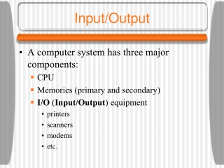
Explore different bus architectures, communication methodologies, and I/O devices. Learn about Intel Pentium's communication, storage systems, and input/output components like keyboards, mice, and displays.

E N D
Principles of Computer ArchitectureMiles Murdocca and Vincent HeuringChapter 8: Input and Output
Chapter Contents • 8.1 Simple Bus Architectures • 8.2 Bridge-Based Bus Architectures • 8.3 Communication Methodologies • 8.4 Case Study: Communication on the Intel Pentium Architecture • 8.5 Mass Storage • 8.6 Input Devices • 8.7 Output Devices
Simple Bus Architecture • • A simplified motherboard of a personal computer (top view):
The Synchronous Bus • • Timing diagram for a synchronous memory read (adapted from [Tanenbaum, 1999]).
The Asynchronous Bus • • Timing diagram for asynchronous memory read (adapted from [Tanenbaum, 1999]).
Bus Arbitration • • (a)Simple centralized bus arbitration; (b) centralized arbitration with priority levels; (c) decentralized bus arbitration. (Adapted from [Tanenbaum, 1999]).
Bridge Based Bus Arch-itecture • • Bridging with dual Pentium II Xeon processors on Slot 2. • (Source: http://www.intel.com.)
Manchester Encoding • • (a) Straight amplitude (NRZ) encoding of ASCII ‘F’; (b) Manchester encoding of ASCII ‘F’.
Magnetic Tape • • A portion of a magnetic tape (adapted from [Hamacher, 1990]).
ECMA-23 Keyboard Layout • • Keyboard layout for the ECMA-23 Standard (2nd ed.). Shift keys are frequently placed in the B row.
Mouse and Trackball • • A three-button mouse (left) and a three-button trackball (right).
Lightpen • • A user selects an object with a lightpen.
Touchscreen • • A user selects an object on a touchscreen.
Joystick • • A joystick with a selection button and a rotatable rod:
Laser Printer • • Schematic of a laser printer (adapted from [Tanenbaum, 1999]).
Cathode Ray Tube • • A CRT with a single electron gun:
Display Controller • • Display controller for a 640´480 color monitor (adapted from [Hamacher et al., 1990]).
VHDL Specification • Interface specification for the majority component • -- Interface • entity MAJORITY is • port • (A_IN, B_IN, C_IN: in BIT • F_OUT: out BIT); • end MAJORITY; • Behavioral model for the majority component • -- Body • architecture LOGIC_SPEC of MAJORITY is • begin • -- compute the output using a Boolean expression • F_OUT <= (not A_IN and B_IN and C_IN) or • (A_IN and not B_IN and C_IN) or • (A_IN and B_IN and not C_IN) or • (A_IN and B_IN and C_IN) after 4 ns; • end LOGIC_SPEC;
VHDL Specification (cont’) • -- Package declaration, in library WORK • package LOGIC_GATES is • component AND3 • port (A, B, C : in BIT; X : out BIT); • end component; • component OR4 • port (A, B, C, D : in BIT; X : out BIT); • end component; • component NOT1 • port (A : in BIT; X : out BIT); • end component; • -- Interface • entity MAJORITY is • port • (A_IN, B_IN, C_IN: in BIT • F_OUT: out BIT); • end MAJORITY;
VHDL Specification (cont’) • -- Body • -- Uses components declared in package LOGIC_GATES • -- in the WORK library • -- import all the components in WORK.LOGIC_GATES • use WORK.LOGIC_GATES.all • architecture LOGIC_SPEC of MAJORITY is • -- declare signals used internally in MAJORITY • signal A_BAR, B_BAR, C_BAR, I1, I2, I3, I4: BIT; • begin • -- connect the logic gates • NOT_1 : NOT1 port map (A_IN, A_BAR); • NOT_2 : NOT1 port map (B_IN, B_BAR); • NOT_3 : NOT1 port map (C_IN, C_BAR); • AND_1 : AND3 port map (A_BAR, B_IN, C_IN, I1); • AND_2 : AND3 port map (A_IN, B_BAR, C_IN, I2); • AND_3 : AND3 port map (A_IN, B_IN, C_BAR, I3); • AND_4 : AND3 port map (A_IN, B_IN, C_IN, I4); • OR_1 : OR3 port map (I1, I2, I3, I4, F_OUT); • end LOGIC_SPEC;