Loads and Load Paths
Loads and Load Paths. " Architecture is inhabited sculpture. " -Constantin Brancusi. Loads and Load Paths. Structural Design Design Loads Dead Load Live Load Snow Load Lateral Loads Load Types Load Combinations Load Path Calculating Beam Loads. Steps in Structural Design.


Loads and Load Paths
E N D
Presentation Transcript
Loads and Load Paths "Architecture is inhabited sculpture." -Constantin Brancusi
Loads and Load Paths • Structural Design • Design Loads • Dead Load • Live Load • Snow Load • Lateral Loads • Load Types • Load Combinations • Load Path • Calculating Beam Loads
Steps in Structural Design • Planning – How will the building be supported? • Establishing the loads • Designing preliminary structural configuration and layout • Analyzing structural members • Selecting preliminary structural members • Evaluating the preliminary design • Redesigning (if needed) – Repeat the above steps as necessary to achieve a safe and efficient design • Designing and detailing the structural components
Design Loads • The load that is assumed for the design of a structure • May include one or more of the following: • Dead Load • Live Load • Snow and Ice Load • Rain Load • Flood Load • Wind Load • Earthquake Load • Earth Pressure Load
Design Loads Dead Loads (DL) – fixed loads • The weight of the building components • The weight of fixed service equipment Photos courtesy www.constructionphotographs.com
Design Loads Live Loads (LL) – transient and moving loads • Loads produced by the use and occupancy of a building • Live load may be variable during a structure’s lifetime • Specified in building codes ©iStockphoto.com ©iStockphoto.com
Design Loads Snow Load • Force of accumulated snow on a roof • Specified in building codes (or local building department) • Depends on • Location • Exposure to wind • Importance of building • Roof slope ©iStockphoto.com
Design Loads Design Snow Load Calculation
Design Snow Load • Find the ground snow load • For Springfield, CO (red dot) the snow load is 15 psf Ground Snow Load in psf • Minimum Snow Load • If , then • If , then
Design Loads Lateral Loads • Wind Loads • Earthquake Loads • Flood Loads • Earth Pressure Loads
Design Loads WIND Wind Load (WL) • Resulting loads yield: • Lateral load on walls • Downward and upward pressure on roofs • Overturning of the structure • Specified in building codes Pressure Uplift Suction
Design Loads Epicenter Earthquake Loads (EQ) • Vertical and lateral forces (dynamic) • Building codes can simplify loading Seismic Forces at Base of Building Hypocenter
Design Loads Flood Loads • Lateral forces resulting from static and dynamic water pressure • Building codes specify that buildings be constructed above the flood elevation or flood-proofed • Design requirements dependent on flood zone Courtesy FEMA BFE (Base Flood Elevation) – The water surface elevation resulting from a flood with a 1% chance of equaling or exceeding that level in any given year Dry flood-proofing: Building must be designed and constructed to be watertight to floodwaters
Design Loads GRADE Soil Pressure Loads • Soil adjacent to a structure will apply a lateral force • Magnitude increases with depth BASEMENT SOIL
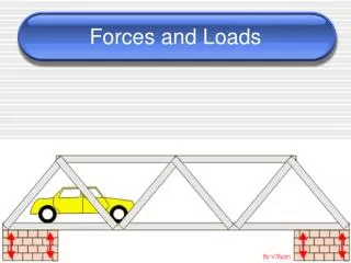
Load Types Uniformly Distributed Load Concentrated Load
Load Combinations • A building will be subjected to many loads simultaneously • Codes specify combinations of loads that must be considered in the design • Examples • D + L + (Lr or S or R) • D + L + W • D + L + S + E/1.4 Where D = Dead load L = Live load Lr = Roof live load W = Wind load S = Snow load E = Earthquake load R = Rain load
Design Loads • The building dead load is the only known load. • All other forces will vary in magnitude, duration, and location. • The building is designed for design load possibilities that may never occur.
Load Path • The path that a load travels through the structural system • “Tracing” or “chasing” the loads • Each structural element must be designed for all loads that pass through it HVAC
Load Path Every load applied to the building will travel through the structural system until it is transferred to the supporting soil. APPLIED LOAD
Structural Elements • Within the structural systems, individual structural elements must work together to carry and transfer the applied loads to the ground. • Examples of structural elements include: • Roof Decking • Elevated Slabs • Load Bearing Walls • Connections • Beams • Girders • Columns • Footing
“Load Chasing” for Structural Design The structural design is performed by “chasing the loads” of the dead and live load from slabs to beams to girders, then on to the columns or walls. The loads are then carried down to the footing or foundation walls and finally to the earth below.
Girder Beam Column Footing Partial View of 2nd Floor Framing For clarity the ground floor slab, 2nd floor slab, roof framing, and roof deck are not shown.
Beam Design Area Girder Partial 2nd FLOOR FRAMING PLAN Girder
3’- 4” Half the distance to each adjacent beam Tributary Area Beam B.3 6’-8” TributaryWidth Partial 2nd FLOOR FRAMING PLAN Tributary Area = Beam Span (length) x Tributary Width
Beam B.3 6'-8'' TributaryWidth Beam Uniform Load = Floor Loading (psf) x Tributary Width (ft)
Beam B.3 6'-8'' TributaryWidth Tributary Area = Beam Span (length) x Tributary Width Tributary Area = (18 ft) ∙ (6.67 ft) = 120 ft2
Calculating Beam Loading Assume that the floor system must support its own weight of 40 psf (dead load) and a live load of 100 psf. What is the uniform load applied to the beam? Total Floor Load = 40 + 100 = 140psf Uniform Load = Floor Load ∙ Tributary Width
Calculating Girder Loading ExteriorGirder Beam DESIGN AREA Interior Girder Partial 2nd FLOOR FRAMING PLAN
Calculating Column Loads Calculating Column Loads Beam Girder
Calculating Column Loads Tributary Area = (18 ft)(20 ft) = 360 ft2
Calculating Column Loads Assume that the floor system must support its own weight of 40 psf (dead load) and a live load of 100 psf. What is the column load for column B3? Total Floor Load = 40 + 100 = 140psf Column Load = Tributary Area ∙ Total Floor Load
Loads and Load Paths • Structural Design • Design Loads • Dead Load • Live Load • Snow Load • Lateral Loads • Load Types • Load Combinations • Load Path • Calculating Beam Loads
Image Sources • iStockphoto.com • www.constructionphotographs.com • Federal Emergency Management Agency