Universal Synchronous/Asynchronous Receiver/Transmitter (USART)
300 likes | 716 Vues
Universal Synchronous/Asynchronous Receiver/Transmitter (USART). Prepared By: Prof. M. B. Salunke SITS, Narhe, Pune - 41. E-mail: msalunke@gmail.com. Communication Modes. The Simplex Mode The Half Duplex Mode The Full Duplex Mode. Communication Methods. Parallel Data Transfer

Universal Synchronous/Asynchronous Receiver/Transmitter (USART)
E N D
Presentation Transcript
Universal Synchronous/Asynchronous Receiver/Transmitter (USART) Prepared By:Prof. M. B. SalunkeSITS, Narhe, Pune - 41. E-mail: msalunke@gmail.com
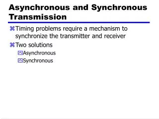
Communication Modes • The Simplex Mode • The Half Duplex Mode • The Full Duplex Mode
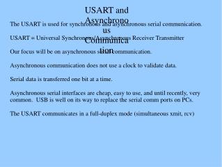
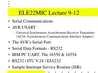
Communication Methods • Parallel Data Transfer • Serial Data Transfer • Synchronous Serial Data Communication • Asynchronous Serial Data Communication
Definitions • Baud Rate: The number of bits per second • Data Terminal Equipment: The originators and receptors of the digital data are called data terminal equipment. E.g. PCs • Data Communication Equipment: The equipment used to transmit or receive data between two DTEs. E.g. Modem
Standards Used in Serial Communication • Current Loop Format • Voltage Signal RS-232C • Earlier 25 Pin Connectors were used • Now a days 9 pin connectors are available 1. Data Carrier Detect 2. Receive Data 3. Transmit Data 4. Data Terminal Ready 5. Signal Ground 6. Data Set Ready 7. Request to Send 8. Clear to send 9. Ring Indicator
USART 8251A: Features • Synchronous and Asynchronous operation • Synchronous 5 – 8 bit character; Internal & External Character Synchronization; Automatic Sync insertion. • Asynchronous 5 – 8 bit character; clock rate 1, 16 or 64 times baud rate; Break character generation; 1, 1.5 or 2 stop bits; False start bit detection; Automatic break Detect and handling. • Synchronous Baud Rate: DC to 64K Baud • Asynchronous Baud Rate: DC to 19.2K Baud
Features continued… • Full duplex, double-buffered transmitter and receiver • Error detection- Parity, overrun and framing • Compatible with an extended range of Intel microprocessors • 28 pin DIP package • TTL Compatible • Available in EXPRESS and Military versions
Functional Description • Data Bus Buffer: 3-state bidirectional buffer, used to interface 8251 and system data bus, • Control words, Command Words, Status information and Data are transferred through it. • Pins D7 – D0
Read/Write Control Logic • This block accepts input from system control bus and generated control signals for overall device operation. • It contains Control Word register and Command Word register. • RESET: HIGH input forces 8251A into an ‘idle’ mode. • CLK: Clock input for internal device timing • WR#: Write • RD#: Read • C/D#: Control/Data • CS#: Chip Select
Modem Control • A set of inputs and outputs used to simplify the interface with modems • DSR#: Data Set Ready: Input used to test modem conditions, such as Data Set Ready. • DTR#: Data Terminal Ready: Output used for modem control, such as Data Terminal Ready. • RTS#: Request To Send: Output used for modem control, such as Request To Send • CTS#: Clear To Send: ‘Low’ input enables the 8251A to transmit serial data if the Tx Enable bit in the command byte is enabled.
Transmitter Section • Section consist of Transmit Buffer and Transmit Control • Transmit buffer accepts parallel data from data bus buffer, convert it to a serial bit stream, insert appropriate characters or bits (based on communication technique) and outputs a composite serial stream of data on the TxD output pin on the falling edge of TxC# • The transmitter will begin transmission upon being enabled if CTS# = 0
Transmitter Section Continued… • Transmit Control manages all activities associated with the transmission of serial data. • TxRDY: Transmitter Ready: Output signals the CPU that transmitter is ready to accept a data character. • TxE: Transmitter Empty: ‘High’ output indicates the 8251A has no characters to send. • TxC#: Transmitter Clock: Controls the rate at which the character is to be transmitted.
Receiver Section • Section consist of Receive buffer and receive control • Receiver Buffer accepts serial data, converts to parallel format, checks for bits or characters that are unique to the communication technique and sends an assembled character to the CPU. • Serial data is input to RxD pin and clocked in on the rising edge of RxC#
Receiver Section Continued… • Receive Control manages all receiver related activities. • The RxD initialization circuit prevents the 8251A an unused input line for an active low data line in the ‘break condition’ • The false start bit detection circuit prevents false starts due to a transient noise spike. • Parity error detection sets the corresponding status bit. • The Framing Error status bit is set if the Stop bit is absent at the end of the data byte (asynchronous mode)
Receiver Section Continued… • RxRDY: Receiver Ready: Output indicates that the 8251A contains a character that is ready to be input to the CPU. • Failure to read character prior to the assembly of the next character will set overrun condition error and previous data will be written over and lost. • RxC#: Receiver Clock: The receiver clock controls the rate at which the character is to be received. • SYNDET/BD: SYNC Detect or Break Detect
Receiver Section Continued… • Used to detect SYNC character/s in case of synchronous mode and for BRKDET in case of asynchronous mode
Programming of 8251 • Controls word are used to programs 8251: Once programmed the 8251 is ready to perform its communication functions. • The control words are split into two formats: • Mode instruction • Command instruction
Programming of 8251A • Mode instruction: Defines the general operational characteristics of the 8251A. • It must follow a reset operation (Internal or External) • Once mode instruction has been written by CPU, SYNC characters or command instructions may be written • Command Instruction: It defines a word that is used to control the actual operation of 8251A • Both instruction must conform the specified sequence for proper device operation