HIGH VOLTAGE TESTING GENERATION AND MEASUREMENTS
1.36k likes | 2.87k Vues
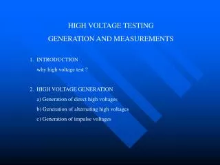
HIGH VOLTAGE TESTING GENERATION AND MEASUREMENTS. 1. INTRODUCTION why high voltage test ? 2. HIGH VOLTAGE GENERATION a) Generation of direct high voltages b) Generation of alternating high voltages c) Generation of impulse voltages. 3. HIGH VOLTAGE MEASUREMENTS

HIGH VOLTAGE TESTING GENERATION AND MEASUREMENTS
E N D
Presentation Transcript
HIGH VOLTAGE TESTING GENERATION AND MEASUREMENTS 1. INTRODUCTION why high voltage test ? 2. HIGH VOLTAGE GENERATION a) Generation of direct high voltages b) Generation of alternating high voltages c) Generation of impulse voltages
3. HIGH VOLTAGE MEASUREMENTS • a) Measurement of direct voltages • b) Measurement of alternating voltages • c) Measurement of impuls voltages • 4. GENERATION OF HIGH IMPULSE CURRENTS • MEASUREMENT OF IMPULS CURRENTS • a) Rogo wski coil method • b) Current shunt method
1. INTRODUCION Difinition : high voltage = voltage > 1 kV Aims of HV test • i) Test HV equipment used in power systems • Non-destructive test (NTD) consist of • Type tests Routine tests • Monitoring tests • Used to measure • Loss angle Partial disharge level • Withstand level • ii) Study of overvoltage effects on equipment • External overvoltages (lightNing) • System overvoltages (switching, temporary)
HIGH VOLTAGE TESTS RELATED STANDARDS AND ORGANISATION • IEC : International Electrotechnical Committee • BSI : British Standard Institution • IEC 60 (Part I and Part II) = BS 923 : high voltage testing techniques • IEC 71 (Part I and Part II) = BS 5622 : insulation Co-ordination • IEC 52 = BS 358 : Method for the measurement of voltage with sphere gaps. • Other bodies • CIGRE : Conférence International des Grands Réseaux Electriques • ISH : International Symposium on High Voltages Engineering
2. HIGH VOLTAGE GENERATION a) Generation Of High Direct Voltage • Existing methods • Rectifier circuits • Multiplier rectifier circuits • Cascaded transformer/rectifier circuits • Special circuits; Engetron, Deltatron • Electrostatic generators
I) Rectifier Circuits : Background definition i) Ripple V : which gives • To reduce ripple • Increase size of smoothing capacitor • Increase frequency • Increase number of phases (if possible) ii) Amlitude V
iii) Ripple Factor iv) Ripple Factor Ripple factor 3 % Regulation Change / variation of voltage 1 minute tests 1% More than 1 minute tests 1%
Voltage doubler circuit Greinacher doubler circuit = (Villard doubler + rectifier/smoothing) circuit Loaded multipliers If unloaded the diodes do not conduct and the ripple is
Because of charge transfer, the capacitors Ci are charged to a voltage equal (Vci - Vi) The total voltage drop is then,
4-stage cascade rectifier Voltages at nodes ‘1’ are oscillating Voltages at nodes ‘1’ are constant 9dc) HV out is 2* 4* Vmax
Vo 2V Loaded cascade circuit, definitions of voltage drop Voand ripple V
GENERATION OF ALTERNATING VOLTAGE i) Test transformer ii) Casaded transformer iii) Resonant circuit I. Test Transformer Simple design ; usually, one side is earthed IEC Standard Specifikations f = 45 – 65 Hz Shape : V (1 minute test) 1% Transformer ratings * dry tests: current rating of 100mA * wet tests: current rating of 500mA * pollution tests: current rating 15 A
Cascaded transformers • Power is shared by the three units • Voltage stress is reduced (shared along the cascade) Basic circuit of cascaded transformers. (1) Primary widings. (2) Seconddary h.t. widings. (3) Tertiary exciting windings.
Series Resonant Circuits For testing large capacitive loads (cable and GIS) and inductive loads (HV reactors) For an RLC series circuit the resonant frequency is The output voltage acros the test object is At resonance, Zc = Zl In practice Zc >> R Which gives V2 >> V1 (20 to 50 times)
Advantages • Better waveshape (fundamental times 50) • Better • rkVA output • Voltage callapse after flashover (no damage to equipment) • Easily cascaded, lighter than transformers.
Resonant Circuits a) Previous designs (no reactors)
GENERATION OF IMPULSE VOLTAGE Why impulse voltage To study the effect of transient overvoltages generated by lightning or swiching operations on the system I. Standard Definition of Lightning Surges T1 front time 1.2 s T2 time to half-value 50 s Surge defined T1/T2 = 1.2 /50 s Tolerances : (IEC60, BS923) peak value 3% front time 30% time to half-value 20%
II. Standard Definition of Switching Surges Tp time to peak (also known as T1) 250 s T2 time to half-value 2500 s TD time above 90% is sometimes specified Surge defined as T1 /T2 = 250/2500 s Tolerances : (IEC60, BS923) peak value 3% front time 20% Time to half-value 60%
With >> • Parameters of V out (t) • Time to peak • Time to half peak value