Data Representation in Computers
Learn about numerical data representation, errors in computations, converting between radix systems, and popular character codes in digital computers. Explore concepts of error-detecting and correcting codes.

Data Representation in Computers
E N D
Presentation Transcript
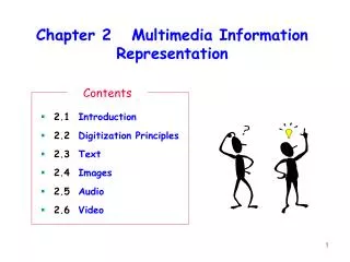
Chapter 2 Data Representation CS140 Computer Organization These slides are derived from those of Null & Lobur + the work of others. Chapter 2: Data Representation
Chapter 2 Objectives • Understand the fundamentals of numerical data representation and manipulation in digital computers – both integer and floating point. • Master the skill of converting between various radix systems. • Understand how errors can occur in computations because of overflow and truncation. • Gain familiarity with the most popular character codes. • Understand the concepts of error detecting and correcting codes. Chapter 2: Data Representation
2.1 Introduction • REVIEW: • A bit is the most basic unit of information in a computer. • It is a state of “on” or “off” in a digital circuit. • Sometimes these states are “high” or “low” voltage instead of “on” or “off..” • A byte is a group of eight bits. • A byte is the smallest possible addressable (can be found via its location) unit of computer storage. • A word is a contiguous group of bytes. • Words can be any number of bits (16, 32, 64 bits are common). • A group of four bits is called a nibble (or nybble). • Bytes, therefore, consist of two nibbles: a “high-order nibble,” and a “low-order” nibble. Chapter 2: Data Representation
2.2 Positional Numbering Systems • Bytes store numbers using the position of each bit to represent a power of 2. • The binary system is also called the base-2 system. • Our decimal system is the base-10 system. It uses powers of 10 for each position in a number. • Any integer quantity can be represented exactly using any base (or radix). • The decimal number 947 in powers of 10 is: • The decimal number 5836.47 in powers of 10 is: 9 10 2 + 4 10 1 + 7 10 0 5 10 3 + 8 10 2 + 3 10 1 + 6 10 0 + 4 10 -1 + 7 10 -2 Chapter 2: Data Representation
2.2 Positional Numbering Systems • Binary works the same as decimal • The binary number 11001 in powers of 2 is: • When the radix of a number is something other than 10, the base is denoted by a subscript. • Sometimes, the subscript 10 is added for emphasis: 110012 = 2510 1 2 4 + 1 2 3 + 0 2 2 + 0 2 1 + 1 2 0 = 16 + 8 + 0 + 0 + 1 = 25 Chapter 2: Data Representation
Suppose we want to convert the decimal number 190 to base 3. We know that 3 5 = 243 so our result will be less than six digits wide. The largest power of 3 that we need is therefore 3 4 = 81, and 81 2 = 162. Write down the 2 and subtract 162 from 190, giving 28. 2.3 Decimal to Binary Conversions Subtraction Method Note: The book also talks about the Division Method which you may prefer. Chapter 2: Data Representation
Converting 190 to base 3... The next power of 3 is 3 3 = 27. We’ll need one of these, so we subtract 27 and write down the numeral 1 in our result. The next power of 3, 3 2 = 9, is too large, but we have to assign a placeholder of zero and carry down the 1. 2.3 Decimal to Binary Conversions Subtraction Method Chapter 2: Data Representation
Converting 190 to base 3... 3 1 = 3 is again too large, so we assign a zero placeholder. The last power of 3, 3 0 = 1, is our last choice, and it gives us a difference of zero. Our result, reading from top to bottom is: 19010 = 210013 2.3 Decimal to Binary Conversions Subtraction Method Chapter 2: Data Representation
2.3 Decimal to Binary Conversions • Fractional values can be approximated in all base systems. • Fractions do not necessarily have exact representations under all radices. • The quantity ½ is exactly representable in binary and decimal, but not in the ternary (base 3) numbering system. • Fractional decimal values have nonzero digits to the right of the decimal point. • Fractional values of other radix systems have nonzero digits to the right of the radix point. 0.4710 = 4 10 -1 + 7 10 -2 0.112 = 1 2 -1 + 1 2 -2 = ½ + ¼ = 0.5+ 0.25 = 0.75 Chapter 2: Data Representation
This shows the subtraction method to convert the decimal 0.8125 to binary. Our result, reading from top to bottom is: 0.812510 = 0.11012 This method works with any base, not just binary. 2.3 Decimal to Binary Conversions Subtraction Method Note: The book also talks about the Multiplication Method which you may prefer. Chapter 2: Data Representation
HEX 2.3 Decimal to Binary Conversions • The binary numbering system is the most important radix system for digital computers. • But, it’s difficult to read long strings of binary numbers-- and even a modest decimal number becomes a very long binary number. • For example: 110101000110112 = 1359510 • For compactness and ease of reading, binary values are usually expressed using the hexadecimal, or base-16, numbering system. • The hexadecimal numbering system uses the numerals 0 through 9 and the letters A through F. • The decimal number 12 is C16. • The decimal number 26 is 1A16. • It is easy to convert between base 16 and base 2, because 16 = 24. • Thus, to convert from binary to hexadecimal, all we need to do is group the binary digits into groups of four. A group of four binary digits is called a hextet Chapter 2: Data Representation
HEX 2.3 Decimal to Binary Conversions • Using groups of hextets, the binary number 110101000110112 (= 1359510) in hexadecimal is: • Practice: Convert 100010 to Hex In hexadecimal, we can’t write numbers 10-16 as single digits, so we use the letters A – F. The number FA316 is F (15) in the 162 column, A (10) in the 161 column and 3 in the 160 column Chapter 2: Data Representation
2.4 Signed Integer Representation • To represent negative values, computer systems allocate the high-order bit to indicate the sign of a value. • The high-order bit is the leftmost bit in a byte. It’s also called the most significant bit. • The remaining bits contain the value of the number. • There are three ways in which signed binary numbers may be expressed: • Signed magnitude, • One’s complement we won’t do much with this here • Two’s complement. Chapter 2: Data Representation
2.4 Signed Integer Representation • In an 8-bit word, signed magnitude representation places the absolute value of the number in the 7 bits to the right of the sign bit. In 8-bit signed magnitude, • Positive 3 is: 00000011 • Negative 3 is: 10000011 • Computers perform arithmetic operations on signed magnitude numbers the same way as humans do pencil and paper arithmetic. • Humans ignore the signs of the operands while doing a calculation, applying the appropriate sign at the end. Chapter 2: Data Representation
2.4 Signed Integer Representation • Binary addition is as easy as it gets. You need to know only four rules: 0 + 0 = 0 0 + 1 = 1 1 + 0 = 1 1 + 1 = 10 • The simplicity of this system makes it possible for digital circuits to carry out arithmetic operations. • We will describe these circuits in Chapter 3. Let’s see how the addition rules work with signed magnitude numbers . . . Chapter 2: Data Representation
2.4 Signed Integer Representation • Example: • Using signed magnitude binary arithmetic, find the sum of 75 and 46. • Convert 75 and 46 to binary, and arrange as a sum. Separate the (positive) sign bits from the magnitude bits. • As in decimal arithmetic, find the sum starting with the rightmost bit and work left. • In the second bit, we have a carry, so we note it above the third bit. Chapter 2: Data Representation
2.4 Signed Integer Representation • Example: • Using signed magnitude binary arithmetic, find the sum of 75 and 46. • The third and fourth bits also give us carries. • Once we have worked our way through all eight bits, we are done. In this example, we were careful to pick two values whose sum would fit into seven bits. If that’s not the case, we have a problem. Example: Using signed magnitude binary arithmetic, find the sum of 107 and 46. • The carry from the seventh bit overflows and is discarded, giving us the erroneous result: 107 + 46 = 25. Chapter 2: Data Representation
2.4 Signed Integer Representation • The signs in signed magnitude representation work just like the signs in pencil and paper arithmetic. • Example: Using signed magnitude binary arithmetic, find the sum of -46 and -25. Because the signs are the same, all we do is add the numbers and supply the negative sign when we are done. • Mixed sign addition (or subtraction) is done the same way. • Example: Using signed magnitude binary arithmetic, find the sum of +46 and -25. The sign of the result gets the sign of the number that is larger. • Note the “borrows” from the second and sixth bits. Chapter 2: Data Representation
2.4 Signed Integer Representation 4-bit Binary Decimal 1000 -8 1001 -7 1010 -6 1011 -5 1100 -4 1101 -3 1110 -2 1111 -1 0000 0 0001 1 0010 2 0011 3 0100 4 0101 5 0110 6 0111 7 • Signed magnitude representation is easy for people to understand, but needs complicated computer hardware. • Another disadvantage: it allows two different representations for zero: positive zero and negative zero. • So computers systems employ complement systems for numeric value representation. Chapter 2: Data Representation
2.4 Signed Integer Representation • To express a value in two’s complement: • If the number is positive, just convert it to binary and you’re done. • If the number is negative, find the one’s complement (change each of the bits) of the number and then add 1. • Example: • In 8-bit one’s complement, positive 3 is: 00000011 • Negative 3 in one’s complement is: 11111100 • Adding 1 gives us -3 in two’s complement form: 11111101. Chapter 2: Data Representation
2.4 Signed Integer Representation • With two’s complement arithmetic, all we do is add our two binary numbers. Just discard any carries emitting from the high order bit. Example: Using two’s complement binary arithmetic, find the sum of +48 and - 19. We note that 19 in one’s complement is:00010011, so -19 in one’s complement is: 11101100, and -19 in two’s complement is: 11101101. Chapter 2: Data Representation
2.4 Signed Integer Representation • When we use any finite number of bits to represent a number, we run the risk of the result of calculations being too large to be stored in the computer. • While we can’t always prevent overflow, we can always detect overflow. Example: Using two’s complement binary arithmetic, find the sum of 107 and 46 (we did this before in slide 17) We see that the nonzero carry from the seventh bit overflows into the sign bit, giving us the erroneous result: 107 + 46 = -103. Rule for detecting signed two’s complement overflow: When the “carry in” and the “carry out” of the sign bit differ, overflow has occurred. Chapter 2: Data Representation
2.4 Signed Integer Representation • Signed and unsigned numbers are both useful. • For example, memory addresses are always unsigned. • Using the same number of bits, unsigned integers can express twice as many values as signed numbers. • Trouble arises if an unsigned value “wraps around.” • In four bits: 1111 + 1 = 0000. • Good programmers stay alert for this kind of problem. Chapter 2: Data Representation
2.4 Signed Integer Representation • There are a number of algorithms that improve the performance of computer arithmetic. • Booth’s algorithm as discussed in the book is one of these enhancements. • Many of these methods are based on the fact that multiplication is HARD for a computer, but addition and shifting is SIMPLE. So techniques that optimize the simple operations make hardware, firmware, software go faster. Chapter 2: Data Representation
2.5 Floating-Point Representation • Integer formats are not useful in scientific or business applications that deal with real number values. • Floating-point representation solves this problem. • Most of today’s computers are equipped with specialized hardware that performs floating-point arithmetic with no special programming required. Chapter 2: Data Representation
2.5 Floating-Point Representation Excess-8 Notation 0000 -8 0001 -7 0010 -6 0011 -5 0100 -4 0101 -3 0110 -2 0111 -1 1000 0 1001 1 1010 2 1011 3 1100 4 1101 5 1110 6 1111 7 Use unsigned magnitude to represent both positive and negative numbers by using a bias, or excess, representation • The entire numbering system is shifted up some positive amount. • To convert a number from excess-8 to decimal. For a number in excess-8, we subtract 8 from the number to get the real value (1001 in excess-8 is 1001 – 1000 = 00012 = +1) • To convert a number from decimal to excess-8. +6 = 01102. Add on the bias like this: 0110 + 1000 = 1110 the is the excess-8 number. • To use the representation • numbers have to be shifted, then stored, and then shifted back when retrieved • Unnecessarily complicated for regular use. • Useful to represent exponents in our floating point representation (shown next) • Detour on biased notation. Chapter 2: Data Representation
2.5 Floating-Point Representation • Floating-point numbers allow an arbitrary number of decimal places to the right of the decimal point. • For example: 0.5 0.25 = 0.125 • They are often expressed in scientific notation. • For example: 0.125 = 1.25 10-1 or 5,000,000 = 5.0 106 Computers use a form of scientific notation for floating-point representation Numbers written in scientific notation have three components: Chapter 2: Data Representation
2.5 Floating-Point Representation Computer representation of a floating-point number consists of three fixed-size fields: • The one-bit sign field is the sign of the stored value. • The size of the exponent field, determines the range of values that can be represented. • The size of the significand determines the precision of the representation. Chapter 2: Data Representation
2.5 Floating-Point Representation • The IEEE-754 single precision floating point standard uses an 8-bit exponent and a 23-bit significand. • The IEEE-754 double precision standard uses an 11-bit exponent and a 52-bit significand. For illustrative purposes, (and to keep life VERY simple) we will use a 14-bit model with a 5-bit exponent and an 8-bit significand. Chapter 2: Data Representation
2.5 Floating-Point Representation • The significand of a floating-point number is always preceded by an implied binary point. • The significand contains a fractional binary value. • The exponent is the power of 2 to which the significand is raised. Example: • Express 3210 in the simplified 14-bit floating-point model. We know that 3210 is 25. So in (binary) scientific notation 3210 = 1.0 x 25 = 0.1 x 26. Using this information, we put 110 (= 610) in the exponent field and 1 in the significand as shown. Chapter 2: Data Representation
The illustrations shown at the right are all equivalent representations for 32 using our simplified model. Not only do these synonymous representations waste space, but they can also cause confusion. 2.5 Floating-Point Representation BUT WAIT – It’s not that simple!! Another problem with our system is that we have made no allowances for negative exponents. We have no way to express 0.5 (=2 -1)! (There is no sign in the exponent field!) All of these problems can be fixed with no changes to our basic model. Chapter 2: Data Representation
To resolve the issue of synonymous forms, we’ll use a rule that the first digit of the significand must be 1. This gives a unique pattern for each number. In the IEEE-754 standard, this 1 is implied meaning that a 1 is assumed after the binary point. By using an implied 1, we increase the precision of the representation by a power of two. (Why?) 2.5 Floating-Point Representation In our simple instructional model, we will not use the implied bits mechanism – the 1 will BE there. To provide for negative exponents, we’ll use a biased exponent (remember our detour??) • We have a 5-bit exponent. We’ll use 16 for our bias. This is called excess-16 representation. In our model, exponent values less than 16 are negative, meaning that the number we’re representing is negative. Chapter 2: Data Representation
2.5 Floating-Point Representation From Decimal to Floating Point. • Example: • Express 3210 in the revised 14-bit floating-point model. • We know that 32 = 1.0 x 25 = 0.1 x 26. • To use our excess 16 biased exponent, we add 16 to 6, giving 2210 (=101102). Example: Express 0.062510 in the revised 14-bit floating-point model. We know that 0.0625 is 2-4. So in (binary) scientific notation 0.0625 = 1.0 x 2-4 = 0.1 x 2 -3. To use our excess 16 biased exponent, we add 16 to -3, giving 1310 (=011012). Chapter 2: Data Representation
2.5 Floating-Point Representation From Decimal to Floating Point. • Example: • Express -26.62510 in the revised 14-bit floating-point model. • We find 26.62510 = 11010.1012. • Normalizing, we have: 26.62510 = 0.11010101 x 2 5. • To use our excess 16 biased exponent, we add 16 to 5, • giving 2110 (=101012). • We also need a 1 in the sign bit. Chapter 2: Data Representation
2.5 Floating-Point Representation From Floating Point to Decimal Exponents will be stored using excess-16 Sign bit = 0 (positive) Exponent = 5 (10101 – 10000 = 5) Significand = .10001000 We shift the decimal point 5 positions giving us 10001.0 = +17 Sign bit = 0 (positive) Exponent = -2 (01110 – 10000 = -2) Significand = .10000000 We shift the decimal point 2 positions to the left, giving us 0.001 = +.125 Sign bit = 1 (negative) Exponent = 3 (10011 – 10000 = 3) Significand = .11010100 We shift the decimal point 3 positions to the right, giving 110.101= -6.625 Chapter 2: Data Representation
2.5 Floating-Point Representation • The IEEE-754 single precision standard uses bias of 127 for its 8-bit exponent. • An exponent of 255 indicates a special value. • If the significand is zero, the value is infinity. • If the significand is nonzero, the value is NaN, “not a number,” often used to flag an error condition. • The double precision standard has a bias of 1023 for its 11-bit exponent. • The “special” exponent value for a double precision number is 2047, instead of the 255 used by the single precision standard. Both the 14-bit model that we have used and the IEEE-754 floating point standard allow two representations for zero. • Zero is indicated by all zeros in the exponent and the significand, but the sign bit can be either 0 or 1. So programmers should avoid testing a floating-point value for equality to zero. • Negative zero does not equal positive zero. Chapter 2: Data Representation
2.5 Floating-Point Representation • Floating-point addition and subtraction are done the same as using pencil and paper. • The first thing that we do is express both operands in the same exponential power, then add the numbers, keeping the exponent in the sum. • If the exponent needs adjustment, fix it at the end. Example: • Find the sum of 1210 and 1.2510 using the 14-bit floating-point model. We find 1210 = 0.1100 x 2 4. And 1.2510 = 0.101 x 2 1 = 0.000101 x 2 4. Thus, our sum is 0.110101 x 2 4. Chapter 2: Data Representation
2.5 Floating-Point Representation • Floating-point multiplication is also the same as pencil and paper. • Multiply the two operands and add exponents. • If the exponent requires adjustment, fix it at the end. Example: • Find the product of 1210 and 1.2510 using the 14-bit floating-point model. We find 1210 = 0.1100 x 2 4. And 1.2510 = 0.101 x 2 1. Thus, our product is 0.0111100 x 2 5 = 0.1111 x 2 4. The normalized product requires an exponent of 2210 = 101102. Chapter 2: Data Representation
2.5 Floating-Point Representation • When discussing floating-point numbers, it is important to understand the terms range, precision, and accuracy. • The range of a numeric integer format is the difference between the largest and smallest values that it can express. • Accuracy refers to how closely a numeric representation approximates a true value. • The precision of a number indicates how much information we have about a value Chapter 2: Data Representation
2.5 Floating-Point Representation • No matter how many bits we use in a floating-point representation, our model must be finite. • The real number system is infinite, so F.P. can give nothing more than an approximation of a real value. • At some point, every model breaks down, introducing errors into our calculations. • By using a greater number of bits in our model, we can reduce these errors, but we can never totally eliminate them. Our job becomes one of reducing error, or at least being aware of the possible magnitude of error in our calculations. Errors can compound through repetitive arithmetic operations. For example, our 14-bit model cannot exactly represent the decimal value 128.5. In binary, it is 9 bits wide: 10000000.12 = 128.510 128.5 - 128 128.5 0.39% Chapter 2: Data Representation
2.5 Floating-Point Representation • Floating-point overflow and underflow can cause programs to crash. • Overflow occurs when there is no room to store the high-order bits resulting from a calculation. • Underflow occurs when a value is too small to store, possibly resulting in division by zero. • The hardware detects the error, causes an interrupt that is caught by the OS which terminates the process. It’s better for a program to crash than to have it produce incorrect, but plausible, results. Chapter 2: Data Representation
2.5 Floating-Point Representation • To test a floating point value for equality to some other number, first figure out how close the numbers can be to be considered equal. • Call this value epsilon and use the statement: if (abs(x - y) < epsilon) then ... Chapter 2: Data Representation
2.6 Character Codes • We use a code to represent characters • EBCDIC – developed for the IBM 360 and used in all IBM mainframes since then • An 8-bit representation for 256 characters • ASCII – used in just about every other computer • A 7-bit representation plus the high-order bit used for parity • Unicode – newer representation to include non-Latin based alphabetic characters • 16 bits allow for 65000+ characters • It is downward compatible with ASCII, so the first 128 characters are the same as ASCII • See figures 2.6-2.8 Chapter 2: Data Representation
2.6 Character Codes • As computers have evolved, character codes have evolved. • Larger computer memories and storage devices permit richer character codes. • The earliest computer coding systems used six bits. • Binary-coded decimal (BCD) was one of these early codes. It was used by IBM mainframes in the 1950s and 1960s. Chapter 2: Data Representation
2.6 Character Codes • In 1964, BCD was extended to an 8-bit code, Extended Binary-Coded Decimal Interchange Code (EBCDIC). • EBCDIC was one of the first widely-used computer codes that supported upper and lowercase alphabetic characters, in addition to special characters, such as punctuation and control characters. • EBCDIC and BCD are still in use by IBM mainframes today. Chapter 2: Data Representation
2.6 Character Codes • Other computer manufacturers chose the 7-bit ASCII (American Standard Code for Information Interchange) as a replacement for 6-bit codes. • While BCD and EBCDIC were based upon punched card codes, ASCII was based upon telecommunications (Telex) codes. • Until recently, ASCII was the dominant character code outside the IBM mainframe world. Chapter 2: Data Representation
2.6 Character Codes • The Unicode codes- space allocation is shown at the right. • The lowest-numbered Unicode characters comprise the ASCII code. • The highest provide for user-defined codes. Chapter 2: Data Representation
2.8 Error Detection and Correction • Overview: • We’re talking about only a tiny fraction of this topic: • Parity • The original Null & Lobur slides, as well as Section 2.8 in the text, do this topic in much more detail. • Simplest approach is to add a parity bit on every byte of information • Add up the number of 1 bits in the byte, add a bit so that the number of total 1s is even • 00101011 has a parity bit of 0, • 11100011 has a parity bit of 1 • With more parity bits, we can not only detect an error, but correct it, or detect 2 errors. • Can also have odd parity where total number of 1s is odd. Chapter 2: Data Representation
Computers store data in the form of bits, bytes, and words using the binary numbering system. Signed integers can be stored in one’s complement, two’s complement, or signed magnitude representation. Floating-point numbers are usually coded using the IEEE 754 floating-point standard. Floating-point numbers may have errors in representation, overflow, & underflow. Character data is stored using ASCII, EBCDIC, or Unicode. Error detecting and correcting codes are necessary because we can expect no transmission or storage medium to be perfect. Chapter 2 Summary Chapter 2: Data Representation
2.8 Error Detection and Correction • These are the original Null & Lobur slides that are included here as reference. We have done only a brief survey of this topic in the lectures. Chapter 2: Data Representation